
Switching power supply circuit

a power supply circuit and circuit technology, applied in the direction of electric variable regulation, process and machine control, instruments, etc., can solve the problems of preventing the load b>4/b> from starting up smoothly, and achieve the effect of reducing the time from start-up driving

Active Publication Date: 2006-07-27
MURATA MFG CO LTD
View PDF7 Cites 12 Cited by
  • Summary
  • Abstract
  • Description
  • Claims
  • Application Information

AI Technical Summary

Benefits of technology

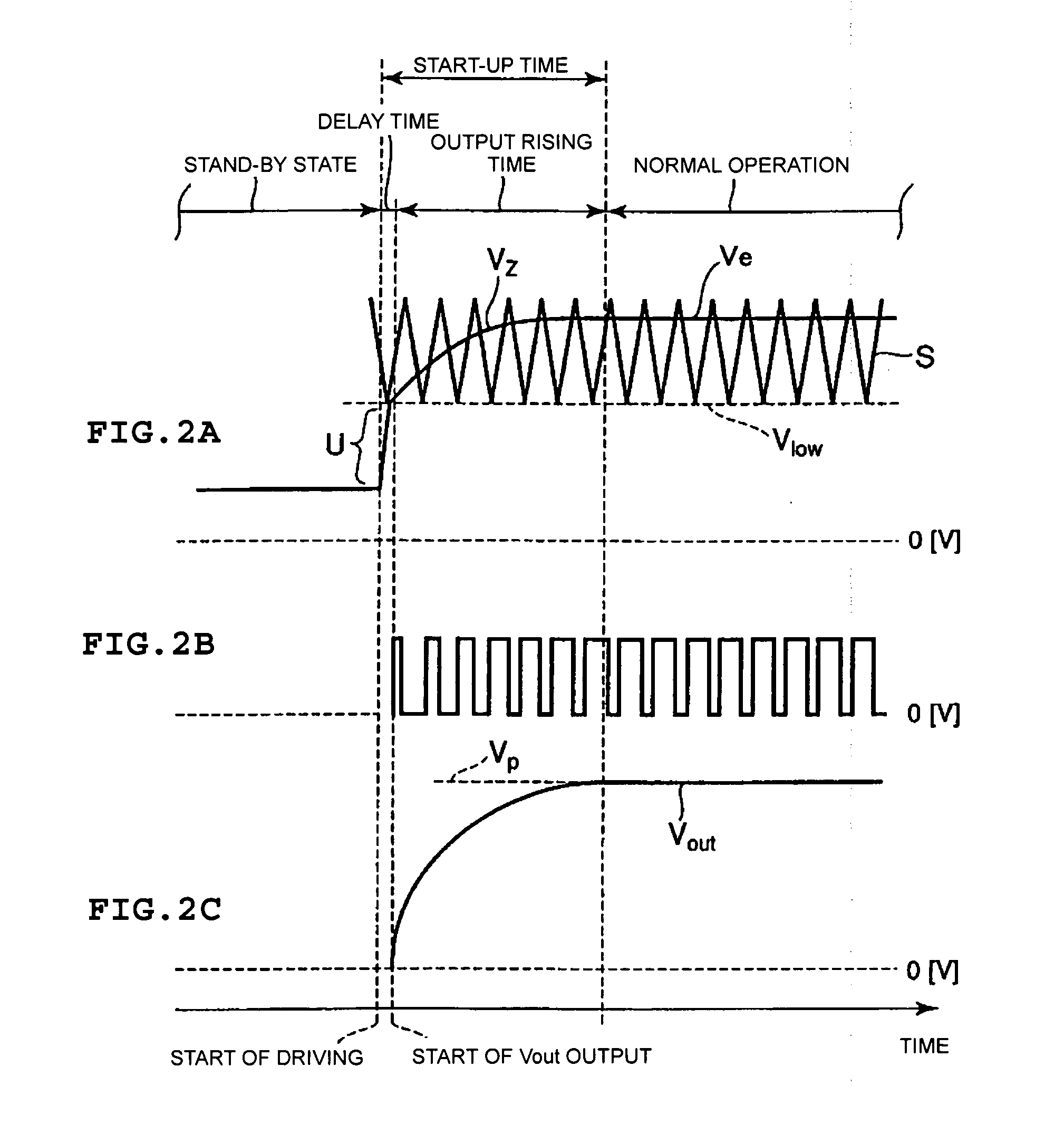
The present invention provides a switching power supply circuit that reduces the time from start-up driving to normal operation while a soft-start is carried out with an output voltage. The circuit includes a main switching element, a soft-start circuit, and a control circuit. The soft-start circuit outputs a soft-start voltage that increases over time during the start-up time. The control circuit starts an output of a switching-control signal based on the soft-start voltage to control the switch ON / OFF operation of the main switching element and cause the output voltage to gently rise towards the normal-operation output voltage. This results in a gentle rising of the output voltage and reduces the delay time from when the switching power supply circuit starts driving to when the output voltage reaches the set normal-operation output voltage.

Problems solved by technology

As a result of the overshoot voltage being applied, a failure, such as latch-up, may occur in the load 4, possibly preventing the load 4 from starting up smoothly.

Method used


Image

  • Switching power supply circuit
  • Switching power supply circuit
  • Switching power supply circuit

Examples


Embodiment Construction

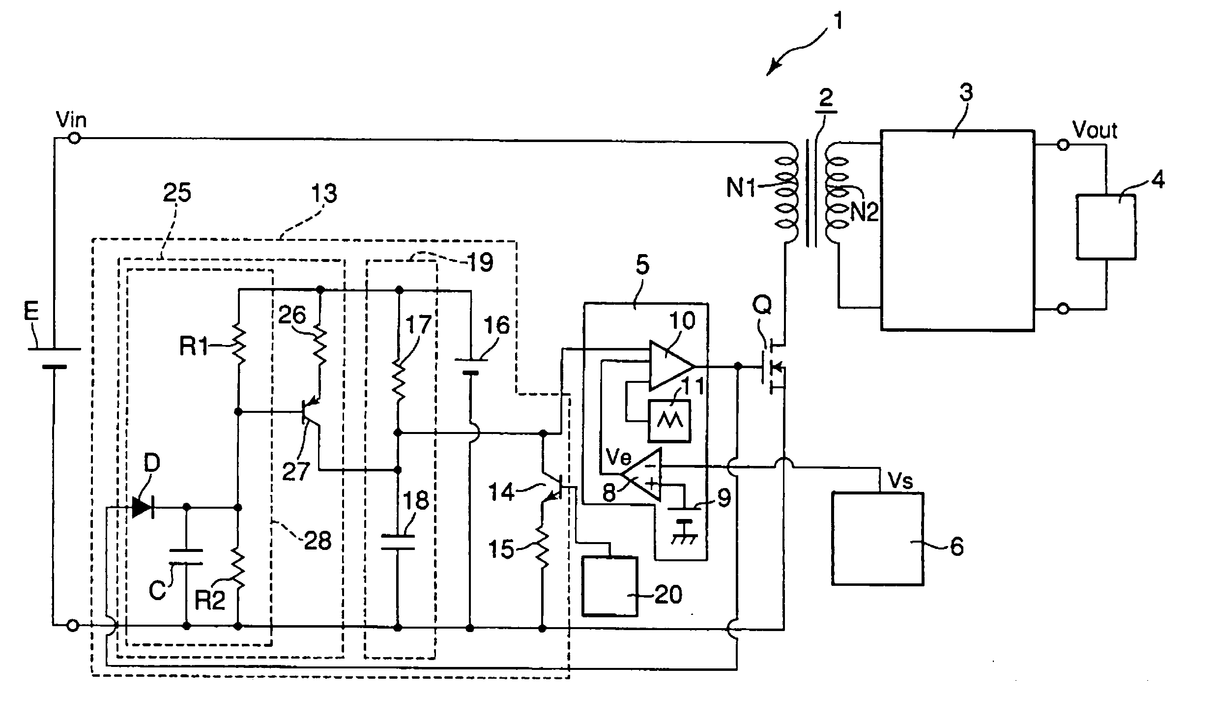
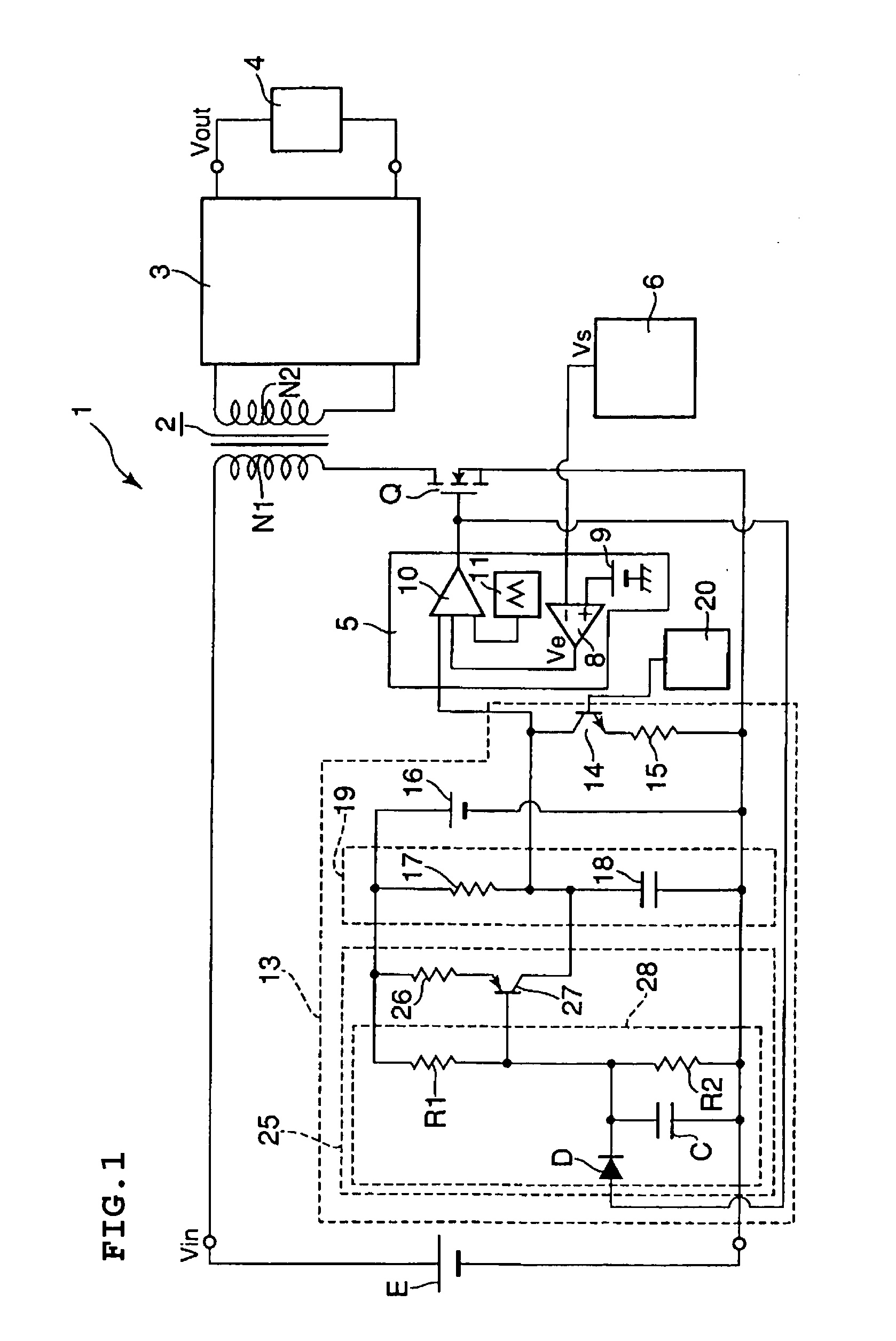
[0032] Various preferred embodiments according to the present invention will now be described with reference to the drawings. In the following preferred embodiments, the components that are the same as or equivalent to those used in the circuit shown in FIG. 6 are denoted by the same reference numerals, and thus such components denoted with the same reference numerals will not be described or will be described only briefly. Furthermore, in cross-reference to other preferred embodiments, the same or equivalent components are denoted by the same reference numerals and components that have been described in a previous preferred embodiment and will not be described or will be described only briefly in another preferred embodiment.

[0033]FIG. 1 shows the main circuit constituent parts of a switching power supply circuit according to a first preferred embodiment of the present invention. A switching power supply circuit 1 according to this first preferred embodiment includes a soft-start ...


PUM


Abstract

A switching power supply circuit reduces the time from start-up driving to normal operation while a soft-start is carried out with an output voltage Vout. A soft-start capacitor is charged during the start-up time. After a soft-start voltage Vz has reached a predetermined signal-output starting voltage Vlow, soft start of the output voltage Vout is carried out by controlling the operation based on the soft-start voltage Vz. A time constant for charging the soft-start capacitor is set as a time constant that causes the charge voltage of the soft-start capacitor to sharply increase at least until the soft-start voltage Vz reaches the signal-output starting voltage Vlow after the circuit has started driving, and is switched to a time constant that causes a rising trend of the charge voltage of the soft-start capacitor to become gentle with a predetermined time-constant switching timing. The start-up time is reduced by an amount equivalent to a reduction in the delay time from the start of driving to the start of voltage output.

Description

BACKGROUND OF THE INVENTION [0001] 1. Field of the Invention [0002] The present invention relates to a switching power supply circuit with a soft-start function for gently raising an output voltage during a start-up time. [0003] 2. Description of the Related Art [0004]FIG. 6 shows one example of a main part of the circuit structure of a switching power supply circuit. This switching power supply circuit 1 includes a transformer 2. A main switching element (e.g., MOSFET) Q is connected in series to a primary coil N1 of this transformer 2. An external input power supply E is connected in parallel to a circuit composed of the primary coil N1 and the main switching element Q connected in series. A secondary rectifying and smoothing circuit 3 is connected to a secondary coil N2 of the transformer 2, and a load 4 is connected to this secondary rectifying and smoothing circuit 3. [0005] A control circuit 5 is connected to the main switching element Q. This control circuit 5 outputs an ON / O...

Claims


Application Information

Patent Timeline
Patent Type & Authority Applications(United States)
IPC IPC(8): H02M3/335H02M1/00H02M1/36H02M3/28
CPCH02M1/36Y10S323/901
Inventor TAKAHASHI, SEIICHINISHIYAMA, TAKAYOSHINAGAI, JUNMOROMIZATO, EITO
Owner MURATA MFG CO LTD
Learn More