Check patentability & draft patents in minutes with Patsnap Eureka AI!

Synchronization device and device for generating a synchronization signal

Inactive Publication Date: 2006-07-27
FRAUNHOFER GESELLSCHAFT ZUR FOERDERUNG DER ANGEWANDTEN FORSCHUNG EV
View PDF10 Cites 18 Cited by
  • Summary
  • Abstract
  • Description
  • Claims
  • Application Information

AI Technical Summary

Benefits of technology

[0009] It is the object of the present invention to provide a synchronization concept reduced in expenditure.
[0036] Preferably, the signal processing means is configured to conduct a correlation (for example a cross-correlation) between the receive signal and a signal correlated with the coarse synchronization signal, so as to detect the coarse synchronization signal in the receive signal. This correlation may be conducted continuously at a low sampling rate, so that the receive signal is searched at reduced expenditure, so as to approximately determine that section of the receive signal in which is located the fine synchronization signal.

Problems solved by technology

Since it is necessary, for accurately determining a position, to send out a broad-band synchronization signal, determining a position is associated with considerable computing complexity, since it is always required to process broad-band signals at a high sampling clock.
If one cross-correlation, for example, is conducted in each test, each test involves a very large number of computing operations which require considerable system resources.
A direct or blind (on-line) search, for example, for a preamble in a broad-band signal is impossible due to this high expenditure.

Method used


Image

  • Synchronization device and device for generating a synchronization signal
  • Synchronization device and device for generating a synchronization signal
  • Synchronization device and device for generating a synchronization signal

Examples


Embodiment Construction

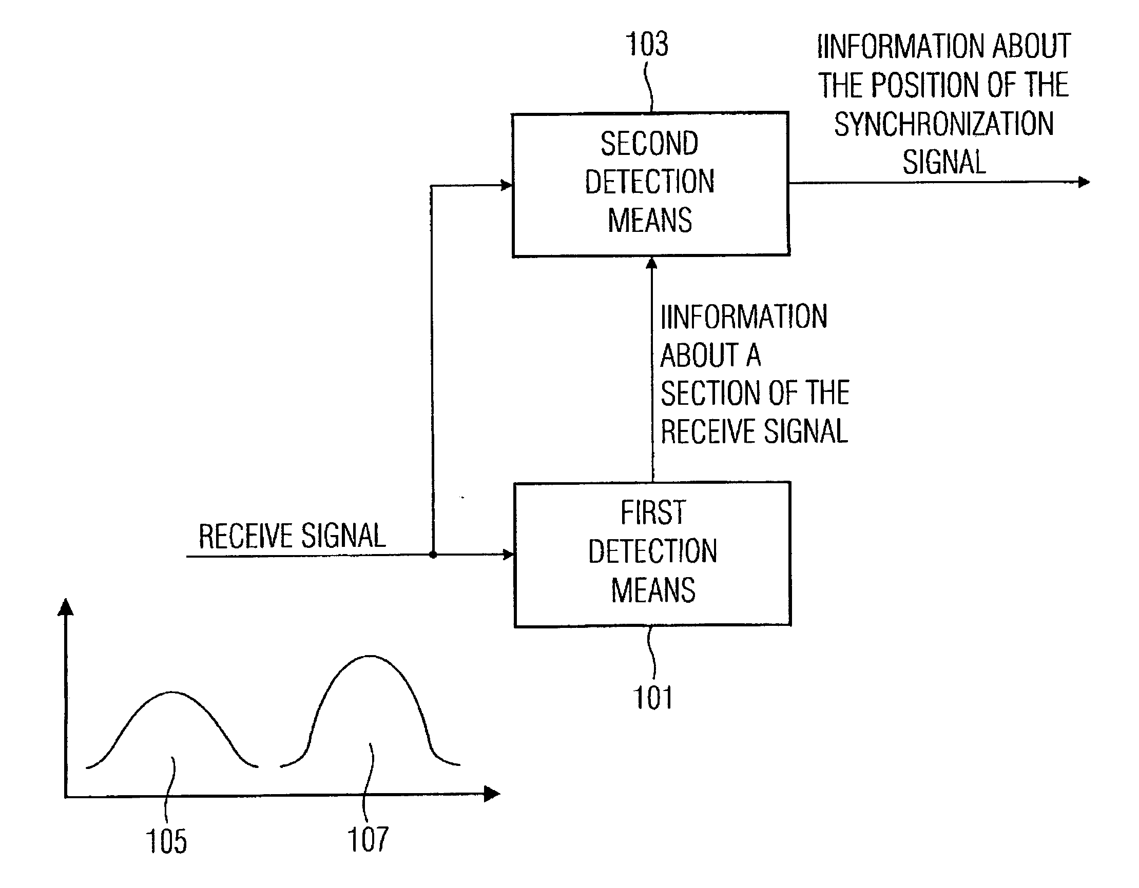
[0060] The synchronization device includes a first detection means 101 with an input, and an output coupled to a second detection means 103. The second detection means includes an input, coupled to the input of the first detection means, and an output.

[0061] In accordance with the invention, a receive signal may be applied to the input of the first detection means 101, it being possible for the receive signal, as is represented in FIG. 1, to include a synchronization signal consisting of a coarse synchronization signal 105 and a fine synchronization signal 107.

[0062] The first detection means 101 is configured to detect the coarse synchronization signal in the receive signal so as to detect that section of the receive signal in which is located the fine synchronization signal. Once the coarse synchronization signal has been detected, the first detection means 101 provides information about a section of the receive signal in which is located the fine synchronization signal to the s...


PUM


Abstract

A synchronization device for determining a position of a synchronization signal in a receive signal, the synchronization signal being based on a coarse synchronization signal and a fine synchronization signal, includes a signal processing means configured to determine, based on the coarse synchronization signal, a section of the receive signal in which is located the fine synchronization signal, and to determine in the section of the receive signal, based on the fine synchronization signal, the position of the synchronization signal in the receive signal for a synchronization.

Description

BACKGROUND OF THE INVENTION [0001] 1. Field of the Invention [0002] The present invention relates to synchronizing a receiver and a transmitter in digital transmission systems. [0003] 2. Description of Prior Art [0004] In digital transmission systems, the information bits to be transmitted are combined into information blocks, each information block corresponding to a frame structure. Each information block includes, in addition to the information bits, a number of additional information bits necessary for effecting the data transmission. [0005] Since the information sent out can be detected with a receiver, in addition to retrieving a sampling clock, it is also necessary to determine the point in time at which point a respective information block is received. In other words, a block synchronization must be conducted in the receiver so as to synchronize the receiver and the transmitter relative to each other. [0006] In order to achieve synchronization, a transmitter sends out, for e...

Claims


Application Information

Patent Timeline
IPC IPC(8): H04L7/00H04W16/28H04W64/00
CPCH04L7/0008H04L7/042H04L7/10H04L27/0014H04L2027/0095
Inventor WAGNER, CARMENKOEHLER, STEFANSTADALI, HOLGERHOFMANN, GUENTERBREILING, MARCO
Owner FRAUNHOFER GESELLSCHAFT ZUR FOERDERUNG DER ANGEWANDTEN FORSCHUNG EV
Features
  • R&D
  • Intellectual Property
  • Life Sciences
  • Materials
  • Tech Scout
  • Unparalleled Data Quality
  • Higher Quality Content
  • 60% Fewer Hallucinations
Learn More