Sound reinforcement system

a sound reinforcement and sound technology, applied in the direction of transducer details, electrical transducers, signal processing, etc., can solve the problems of excessive sound reinforcement, inability to uniformly reinforce sound throughout the room, and excessive sound reinforcement in the vicinity of a person speaking, etc., to achieve high-quality sound reinforcement

Inactive Publication Date: 2006-07-27
YAMAHA CORP
View PDF13 Cites 113 Cited by
  • Summary
  • Abstract
  • Description
  • Claims
  • Application Information

AI Technical Summary

Benefits of technology

[0025] It is a first object of the present invention to provide a sound reinforcement system that enables handsfree and high-quality sound reinforcement without requiring a person who is speaking to move to a microphone or move a microphone.

Problems solved by technology

However, in the case where speakers are concentrated at one point, picked-up sound is excessively reinforced in the vicinity of the speakers, and also, in the case where speakers are arranged at dispersed locations, picked-up sound is excessively reinforced in the vicinity of a person who is speaking.
Thus, sound cannot be uniformly reinforced throughout a room.
Also, it has been difficult to reinforce sound of a plurality of channels due to a risk of howling.
In this case, the listener may feel discomfort.
This causes the listener to feel discomfort since the sense of sight and the sense of hearing are inconsistent with each other.
Also, in a sound reinforcement system in which an input signal from a microphone is amplified and reinforced from speakers arranged in the same space such a conference room or a hall, sound from the speakers may pass to the microphone to form a closed loop, which causes howling.
Also, when the gain of sound reinforcement is decreased for the purpose of preventing howling, sound cannot be reinforced at a satisfactory level.
Further, signal processing using a howling canceller as described above has also been known, but this is not effective since the transfer function cannot be estimated where microphones of a plurality of channels are used, although this is effective in the case where a microphone of only one channel is used.
Also, to accommodate a plurality of channels, a complicated and expensive system is required.

Method used


Image

  • Sound reinforcement system
  • Sound reinforcement system
  • Sound reinforcement system

Examples


first embodiment

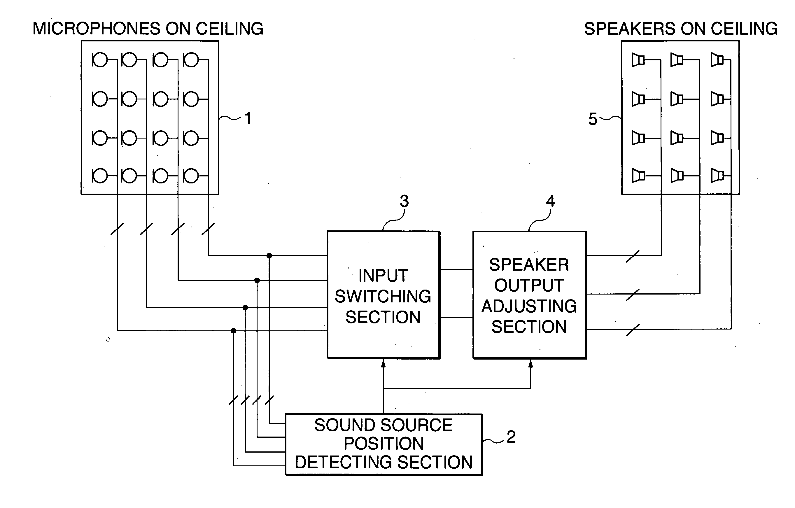
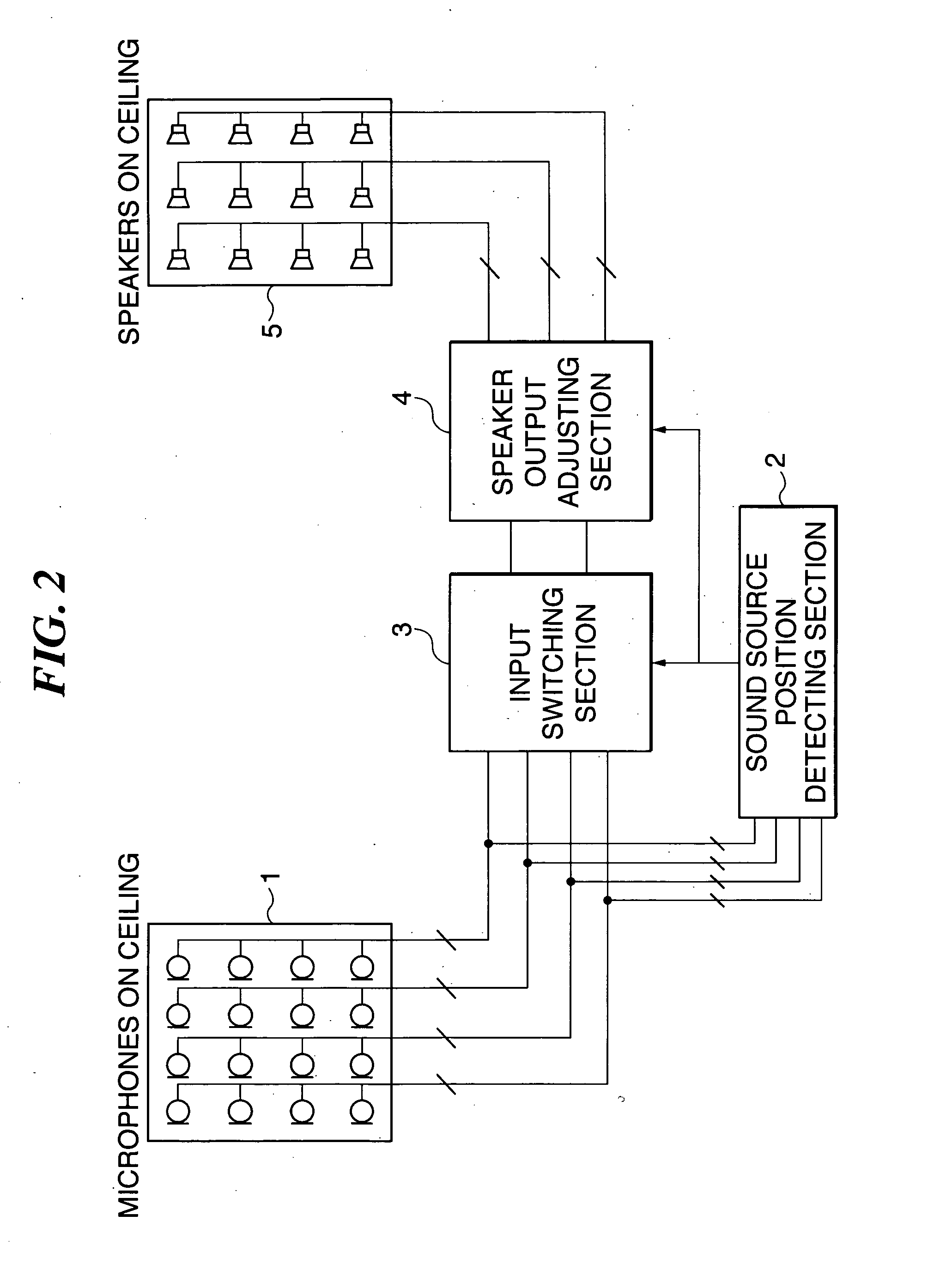
[0072]FIG. 2 is a block diagram showing the overall configuration of a sound reinforcement system according to the present invention. This sound reinforcement system can be suitably applied to small-to-medium sized conference rooms or the like where all the listeners cannot hear speech well only by speaker's real voice.

[0073] In FIG. 2, reference numeral 1 denotes a plurality of (m) microphones arranged at dispersed locations on the ceiling of a room equipped with the sound reinforcement system according to the present invention, and reference numeral 5 denotes a plurality of (n) speakers arranged at dispersed locations on the ceiling similarly to the microphones. Each of the microphones1 (MIC1 to MICm) has a directivity that is limited to pick up sound only within an area in its vicinity, and the m microphones 1 arranged at dispersed locations on the ceiling cover the entire room. Similarly, each of the speakers 5 (SP1 to SPn) has a directivity that is limited to reinforce sound wi...

second embodiment

[0123]FIG. 8 is a block diagram showing the configuration of the sound reinforcement system according to the present invention more concretely. In the sound reinforcement system in FIG. 8, input signals of up to two channels can be processed at the same time.

[0124] In FIG. 8, component elements corresponding to those appearing in FIG. 3A and FIG. 5 referred to above are denoted by the same reference numerals, and description thereof is omitted.

[0125] Input signals corresponding to sound picked up by a plurality of microphones 1 (MIC1 to MICm) arranged at dispersed locations on the ceiling as described above are amplified by the head amplifier group 11 and then converted into digital data by the A / D converter 12. The input signals from the respective microphones 1 are output from the A / D converter 12 and input to the sound source position detecting section 2 and the speaker's face direction detecting section 23 as well as the input switching section 3.

[0126] As described above, the...

third embodiment

[0137]FIG. 9 is a block diagram showing the overall configuration of a sound reinforcement system according to the present invention.

[0138] The same component elements of the sound reinforcement system according to the third embodiment as those of the sound reinforcement system according to the first embodiment described above are denoted by the same reference numerals, and description thereof is omitted.

[0139] In FIG. 9, reference numeral 1 denotes a plurality of (m) microphones arranged at dispersed locations on the ceiling of a conference room, a hall, or the like equipped with the sound reinforcement system according to the present embodiment, and reference numeral 5 denotes a plurality of (n) speakers arranged at dispersed locations on the ceiling similarly to the microphones 1.

[0140] In FIG. 9, reference numeral 32 denotes a sound source position and speech order detecting section that monitors the levels of input signals from respective ones (MIC1 to MICm) of the plurality ...


PUM


Abstract

A sound reinforcement system which enables handsfree and high-quality sound reinforcement without requiring a person who is speaking to move to a microphone or move a microphone. At least one microphone and a plurality of speakers are arranged in a room. A speaker output adjusting section outputs sound picked up by the microphone to the plurality of speakers at predetermined levels.

Description

BACKGROUND OF THE INVENTION [0001] 1. Field of the Invention [0002] The present invention relates to a sound reinforcement system, and more particularly to a sound reinforcement system which can be suitably applied to small-to-medium conference rooms. [0003] 2. Description of the Related Art [0004] When a person who is speaking and the audience are in the same room above a certain size, and the audience cannot hear sound made by the person who is speaking well only by real voice, the sound needs to be reinforced and made audible throughout the room. [0005] In general, in the case where sound is reinforced, a person who speaks has to speak in front of a fixed microphone, or a person who is speaking carries a microphone so that clear sound can be picked up. When speakers are changed during, for example, a question-and-answer session, a person who asks questions has to move to a fixed microphone, or a microphone has to be moved to him / her. [0006] In many cases, speakers concentrated at...

Claims


Application Information

Patent Timeline
Patent Type & Authority Applications(United States)
IPC IPC(8): H04R29/00H04R3/00
CPCH04R3/005H04R3/02H04R2201/401H04R2430/20
Inventor MIKI, AKIRAITO, ATSUKO
Owner YAMAHA CORP
Why Eureka
Try Eureka