Development apparatus and image forming apparatus comprising the same

a technology of development apparatus and image forming apparatus, which is applied in the direction of electrographic process apparatus, instruments, optics, etc., to achieve the effect of stable developer discharg

Active Publication Date: 2006-07-27
SHARP KK
View PDF4 Cites 36 Cited by
  • Summary
  • Abstract
  • Description
  • Claims
  • Application Information

AI Technical Summary

Benefits of technology

[0044] An action which propels the developer in the transport direction and an action which raises the developer are subtly balanced and the height of the developer level is likely to be unstable at a position where the developer has difficulty in flowing, i.e., a position where the gap between the flow regulating member and the side wall of the development container is narrow. Therefore, when the developer discharge outlet is provided in such a position, developer discharge is likely to be unstable. Therefore, it is preferable that the developer discharge outlet is provided at the above-described position, thereby making it possible

Problems solved by technology

In addition, even when the development apparatus is tilted so that the developer discharge outlet is positioned lower and the developer is une

Method used


Image

  • Development apparatus and image forming apparatus comprising the same
  • Development apparatus and image forming apparatus comprising the same
  • Development apparatus and image forming apparatus comprising the same

Examples


Embodiment Construction

[0063] Hereinafter, embodiments of the present invention will be described with reference to the accompanying drawings for the purpose of understanding of the present invention. Note that the following embodiments of the present invention are only for illustrative purposes and are not intended to limit the technical scope of the present invention.

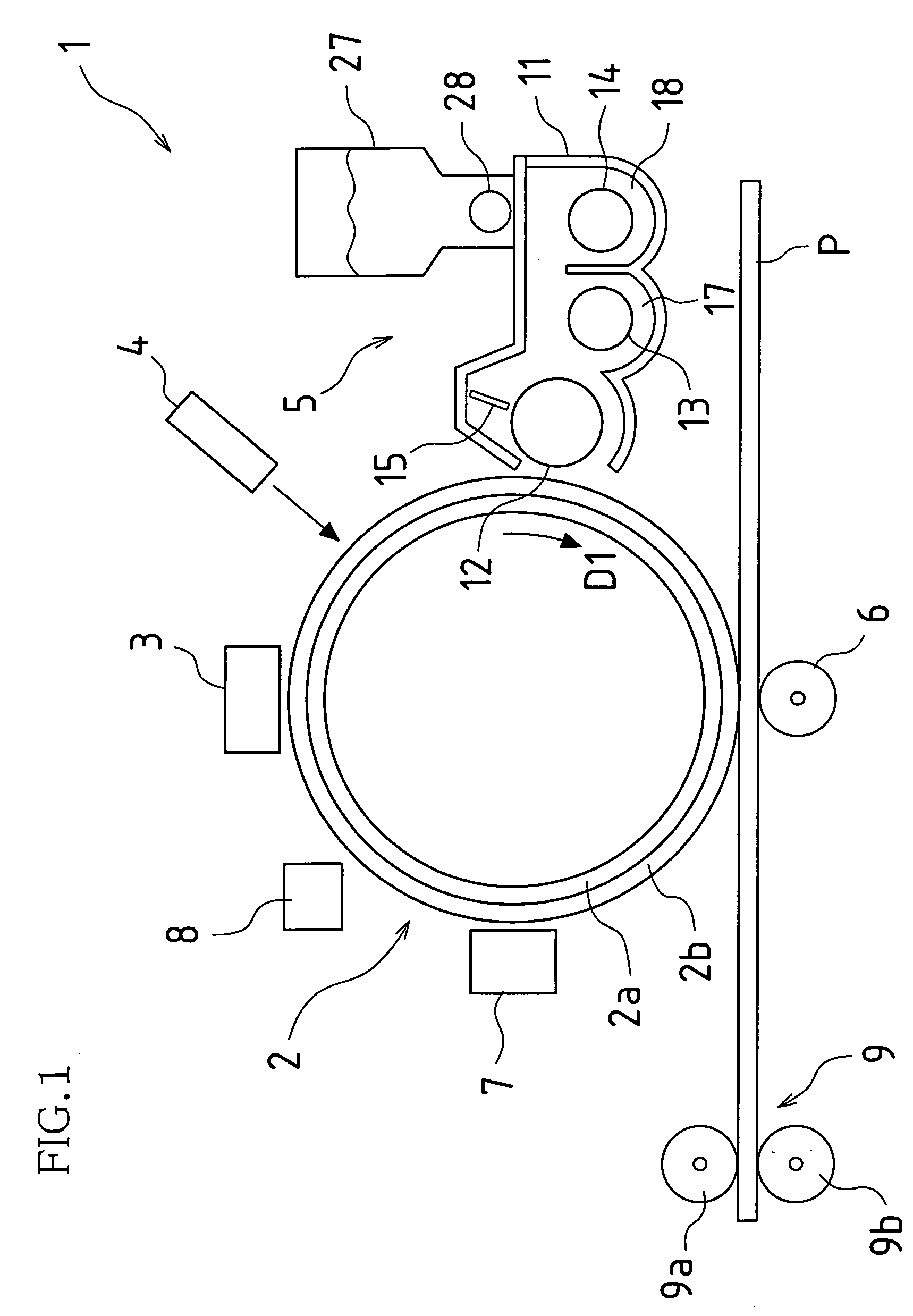
[0064]FIG. 1 is a schematic diagram illustrating a rough structure of an electrophotographic image forming apparatus to which a development apparatus according to an embodiment of the present invention is applied. As illustrated in FIG. 1, the image forming apparatus 1 comprises a photosensitive body 2, a charging member 3, an exposing member 4, a development apparatus 5, a transfer member 6, a cleaning member 7, a charge removal member 8, and a fixing apparatus 9. The charging member 3, the exposing member 4, the development apparatus 5, the transfer member 6, the cleaning member 7, and the charge removal member 8 are provided in this ord...


PUM


Abstract

A development apparatus according to an embodiment comprises a development tank which accommodates developer containing toner and carrier, an agitating screw which agitates and transports the developer in the development tank, and a development roller which is provided close to or in contact with a photosensitive body and visualizes an electrostatic latent image on the photosensitive body. The toner and the carrier are externally replenished to the development tank, and excess developer in the development tank is discharged through a developer discharge outlet to outside of the development container. In the development container, the development apparatus further comprises a flow regulating member for regulating a flow of the developer. The flow regulating member is provided facing the developer discharge outlet and extending vertically upward with respect to a bottom plane of the development tank.

Description

CROSS REFERENCE TO RELATED APPLICATIONS [0001] This application claims priority under 35 U.S.C. §119(a) on Patent Application No. 2005-18359 filed in Japan on Jan. 26, 2005, the entire contents of which are hereby incorporated by reference. BACKGROUND OF THE INVENTION [0002] 1. Field of Invention [0003] The present invention relates to a development apparatus which is used in an image forming apparatus, such as a copier, a printer, a facsimile machine, or the like, and visualizes an electrostatic latent image formed on an image carrier using developer, and an image forming apparatus comprising the same. More particularly, the present invention relates to a so-called trickle development apparatus which employs two-component developer containing toner and carrier, and supplies the toner and the carrier while discharging excess developer, and an image forming apparatus comprising the same. [0004] 2. Related Art [0005] There is a known development apparatus which comprises a development...

Claims


Application Information

Patent Timeline
IPC IPC(8): G03G15/08
CPCG03G15/0844G03G21/105
Inventor ADACHI, KATSUMI
Owner SHARP KK
Why Eureka
Try Eureka