
Bellows Pump

a belt-type pump and belt-type technology, applied in the direction of pump components, positive displacement liquid engines, pulse equalisation, etc., can solve the problems of shortened pump life, loosened bolts may slip off, and pump failure to normally operate, etc., to reduce pump performance, shorten pump life, and increase sliding resistance

Inactive Publication Date: 2006-07-27
NIPPON PILLAR PACKING CO LTD
View PDF3 Cites 19 Cited by
  • Summary
  • Abstract
  • Description
  • Claims
  • Application Information

AI Technical Summary

Benefits of technology

[0009] In a conventional bellows pump, a flange and bolts are used for coupling a pump bellows with a coupling shaft. When several of the bolts are loosened or fastening torques of the bolts are uneven, the axis of the pump bellows is deviated from that of the coupling shaft, thereby causing the following problems. A sliding portion of the coupling shaft is unevenly worn, and therefore the life period of the pump is shortened. The sliding resistance is increased, and therefore the pump performance is lowered. Moreover, there is a fear that loosened bolts may slip off. In this case, the pump fails to normally operate. Furthermore, the numbers of components and assembly steps are increased, and the torques of fastening portions must be managed. Therefore, there are further problems such as that they may produce causes of impeding improvement of the productivity of the pump, and cost reduction.
[0010] Moreover, nuts and bolts are used in coupling of a coupling shaft with a piston or a coupling plate. Therefore, a gap is produced between the coupling shaft and the piston or the coupling plate by dimensional tolerances. This gap may cause the coupling shaft and the piston or the coupling plate to be fastened in a state where their axes are deviated from each other. Therefore, a sliding portion of the piston is unevenly worn, or the coupling plate obliquely applies a load to the coupling shaft, so that a sliding portion of the coupling shaft is unevenly worn, and the life period of the pump is shortened. The sliding resistance is increased, and therefore the pump performance is lowered. Moreover, there is a fear that loosened bolts may slip off. In this case, the pump fails to normally operate. Furthermore, the numbers of components and assembly steps are increased, and the torques of fastening portions must be managed. Therefore, there are further problems such as that they may produce causes of impeding improvement of the productivity of the pump, and cost reduction.
[0011] It is a first object of the invention to provide a bellows pump in which a shaft that is to couple a pump bellows with a piston or a coupling plate can be coupled with the pump bellows on the same axis without using a flange and a plurality of bolts, whereby the life period of the pump can be prolonged, the pump performance can be maintained for a long term, and compactification and cost reduction of the pump can be realized. It is a second object of the invention to provide a bellows pump in which a shaft that is to couple a pump bellows with a piston or a coupling plate can be coupled with the piston or the coupling plate on the same axis without using nuts and bolts in the piston or the coupling plate, whereby the life period of the pump can be prolonged, the pump performance can be maintained for a long term, and compactification and cost reduction of the pump can be realized.

Problems solved by technology

When several of the bolts are loosened or fastening torques of the bolts are uneven, the axis of the pump bellows is deviated from that of the coupling shaft, thereby causing the following problems.
A sliding portion of the coupling shaft is unevenly worn, and therefore the life period of the pump is shortened.
Moreover, there is a fear that loosened bolts may slip off.
In this case, the pump fails to normally operate.
Therefore, there are further problems such as that they may produce causes of impeding improvement of the productivity of the pump, and cost reduction.
Therefore, a sliding portion of the piston is unevenly worn, or the coupling plate obliquely applies a load to the coupling shaft, so that a sliding portion of the coupling shaft is unevenly worn, and the life period of the pump is shortened.
Moreover, there is a fear that loosened bolts may slip off.
In this case, the pump fails to normally operate.
Therefore, there are further problems such as that they may produce causes of impeding improvement of the productivity of the pump, and cost reduction.

Method used


Image

  • Bellows Pump
  • Bellows Pump
  • Bellows Pump

Examples


first embodiment

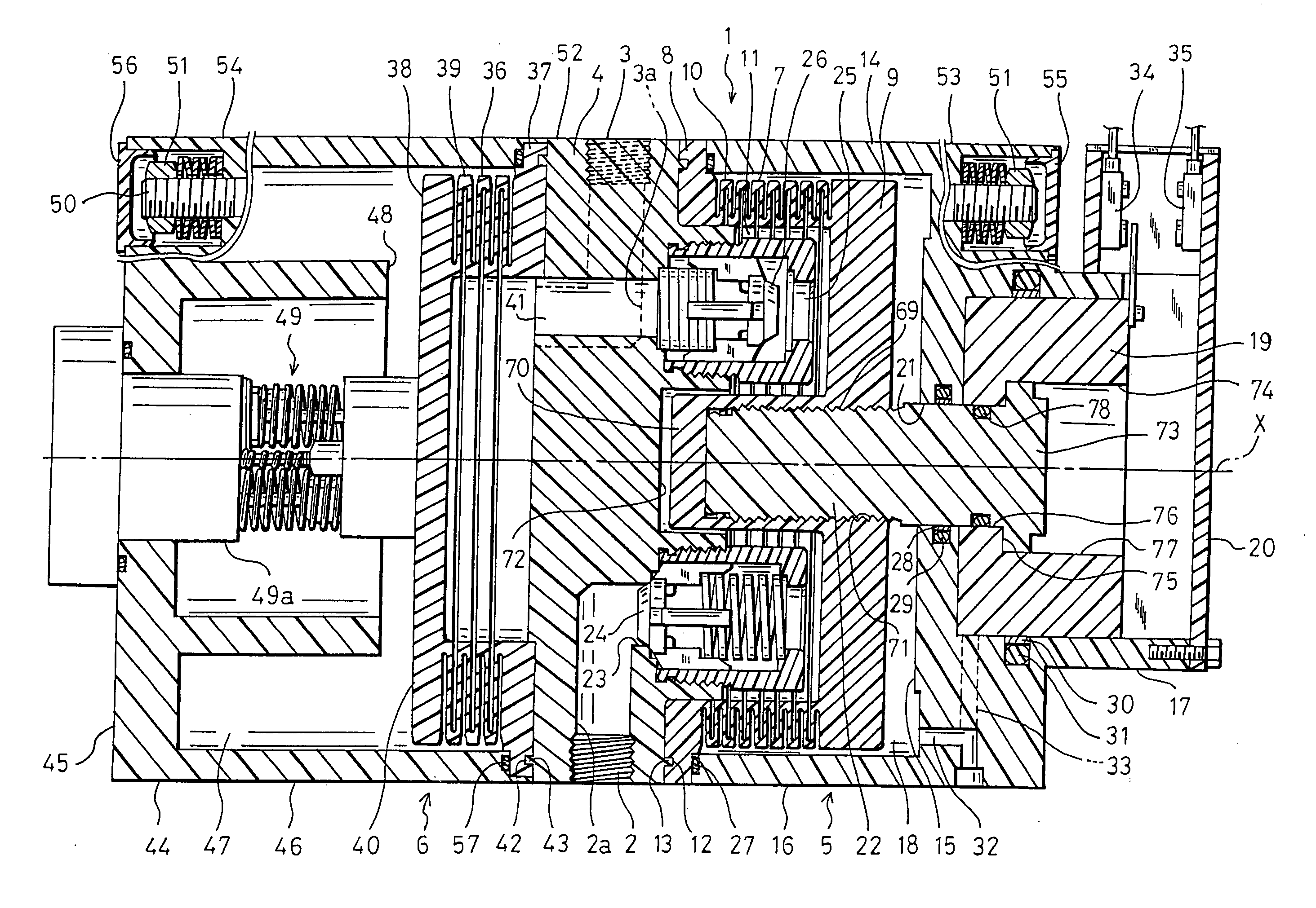
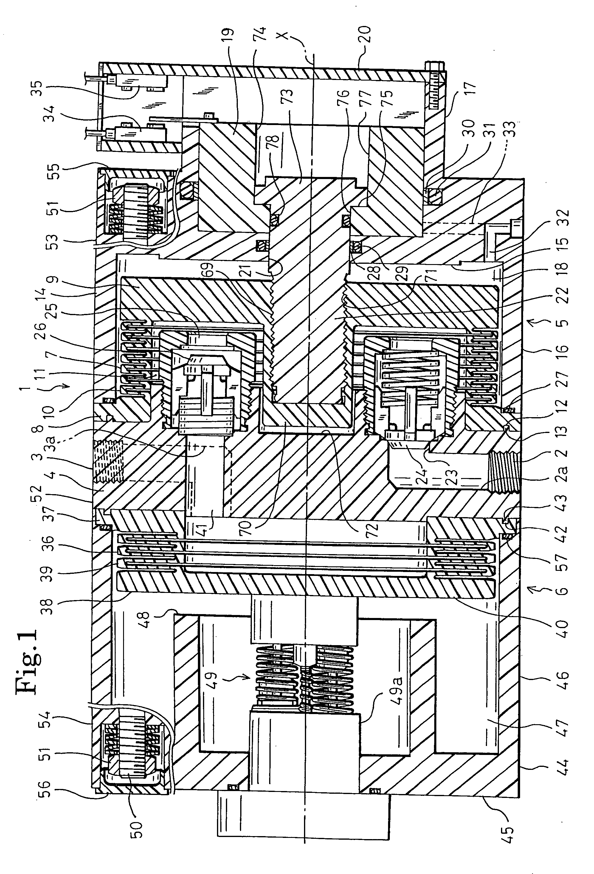
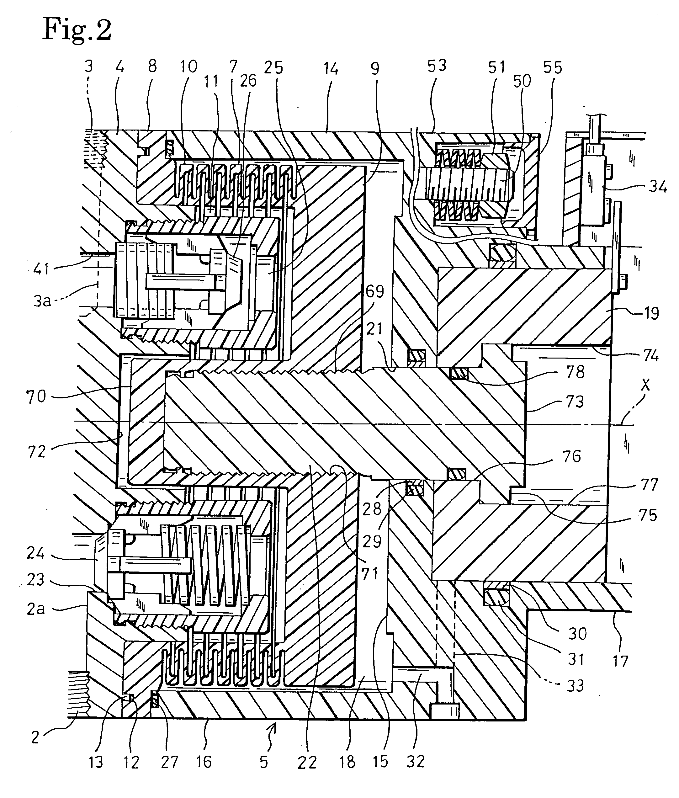
[0023] Hereinafter, embodiments of the invention will be described with reference to the accompanying drawings. FIG. 1 is a section view showing an internal structure of a bellows pump of the invention, and FIG. 2 is an enlarged view of a pump unit shown in FIG. 1. The bellows pump 1 is used as a pump for transporting a liquid such as a chemical liquid, a solvent, or pure water in, for example, a semiconductor manufacturing factory, and is configured by: a pump body 4 which is a substantially square plate-like pump head, and in which suction and discharge ports 2 and 3 for the transported liquid are formed; a pump unit 5 which is placed on one side (the right side in FIG. 1) of the pump body 4; and an accumulator unit 6 which is placed on the other side (the left side in FIG. 1) of the pump body 4.

[0024] A pump bellows 7 which can extend and contract in the axial direction (the lateral direction in FIG. 1) is placed in one side portion (the right side portion in FIG. 1) of the pump ...

second embodiment

[0037] The bellows pump 58 of the second embodiment is configured by the pump body 4, and a pair of pump units 5 which are placed on both sides (the right and left sides in FIG. 3) of the pump body 4 on the same axis X, respectively. In each of the pump units 5, the piston 19 is formed to have a diameter which is larger than the outer diameter of the first cylinder section 16 of the pump cylinder 14, and, in accordance with this, also the second cylinder section 17 is formed to have a diameter which is larger than the outer diameter of the first cylinder section 16. The pistons 19 of the pump units 5 are fastened together by plural metal tie rods 59 which are in parallel to the axis X, in the radially outer side of the first cylinder sections 16. In each of the tie rods 59, steps 59a, 59b are formed in end portions, respectively. The steps 59a, 59b enable the pistons 19 of the pump units 5 to be coupled together with maintaining a predetermined distance between the pistons. The inte...

third embodiment

[0049] As apparent from the above description, in summary, the bellows pump 67 of the third embodiment comprises: the pump body 4 in which suction and discharge ports 2 and 3 for the transported liquid are formed; and the pair of pump units 5 which are placed on both sides of the pump body 4, respectively. Each of the pump units 5 comprises: the bottomed cylindrical pump bellows 7 which is placed so that the open end portion 8 is joined to the pump body 4 in one side portion of the pump body 4 to internally form the pump chamber 11, and which can axially extend and contract; the pump cylinder 14 configured by the cylinder head portion 15 which is placed opposingly to the pump body 4 in the axially outside of the pump bellows 7, and the first cylinder section 16 which is projected on the same axis X as the pump bellows 7 from the cylinder head portion 15 toward the pump body 4 so as to internally accommodate the pump bellows 7, which is opposed in the open end portion to the pump bod...


PUM


Abstract

The present invention relates to, among bellows pumps for transporting a liquid with using a bellows which axially extends and contracts, a so-called internal-liquid type bellows pump in which an air chamber is formed outside a bellows and a liquid to be transported is sucked into the bellows. In order to prevent a pump bellows, a piston or coupling plate, and a shaft coupling them from being deviated from the same axis, prolong the life period of the pump, maintain the pump performance for a long term, and realize compactification and cost reduction of the pump, an external thread is formed on the outer face of one end side of the shaft, an engagement head is formed on the other end, a bottomed cylindrical shaft screwed portion which is projected from a center portion of the bottom into the pump bellows on the same axis, and which has an internal thread on an inner face is disposed in a bottomed cylindrical pump bellow, and the one end side of the shaft is directly coupled with a center portion of the pump bellows by thread joining.

Description

BACKGROUND OF THE INVENTION [0001] 1. Field of the Invention [0002] The present invention relates to, among bellows pumps for transporting a liquid with using a bellows which axially extends and contracts, a so-called internal-liquid type bellows pump in which an air chamber is formed outside a bellows and a liquid to be transported is sucked into the bellows. [0003] 2. Description of the Prior Art [0004] Conventionally, a bellows pump of such a kind is used as a pump for transporting a liquid such as a chemical liquid, a solvent, or pure water in a semiconductor manufacturing factory. For example, bellows pumps of such a kind are classified into the following two categories. [0005] The first one is a bellows pump such as disclosed in Japanese Patent Application Laying-Open No. 2001-317449. The conventional bellows pump comprises: a pump body in which suction and discharge ports for a liquid to be transported (hereinafter, referred to as transported liquid) are formed; a pump unit w...

Claims


Application Information

Patent Timeline
Patent Type & Authority Applications(United States)
IPC IPC(8): F04B45/02
CPCF04B11/0016F04B43/084F04B43/10
Inventor TESHIMA, KAZUKIYO
Owner NIPPON PILLAR PACKING CO LTD
Learn More