Environmental barrier coating with physical barrier layer for silicon-comprising materials

a technology of environmental barrier and physical barrier layer, which is applied in the field of coating system, can solve the problems of ysz not adhering well to si-comprising materials (sic or silicon), mullite exhibits significant silica activity and volatilization, and the engine's high temperature durability must correspondingly increas

Active Publication Date: 2006-07-27
GENERAL ELECTRIC CO
View PDF40 Cites 38 Cited by
  • Summary
  • Abstract
  • Description
  • Claims
  • Application Information

AI Technical Summary

Benefits of technology

The technical effect of this patent is that it seeks to find ways to protect environmental barrier coatings with a porous surface structure from damage caused by external pollutants like CMAS.

Problems solved by technology

The technical problem addressed in this patent text is how to protect environmental barrier coatings used on gas turbine engine components from the damaging effect of environmental contaminants like CMAS, which can lead to cracking and failure of the coating under certain circumstances.

Method used


Image

  • Environmental barrier coating with physical barrier layer for silicon-comprising materials
  • Environmental barrier coating with physical barrier layer for silicon-comprising materials

Examples


Embodiment Construction

[0017] As used herein, the term “comprising” means various compositions, compounds, components, layers, steps and the like can be conjointly employed in the present invention. Accordingly, the term “comprising” encompasses the more restrictive terms “consisting essentially of” and “consisting of.”

[0018] All amounts, parts, ratios and percentages used herein are by weight unless otherwise specified.

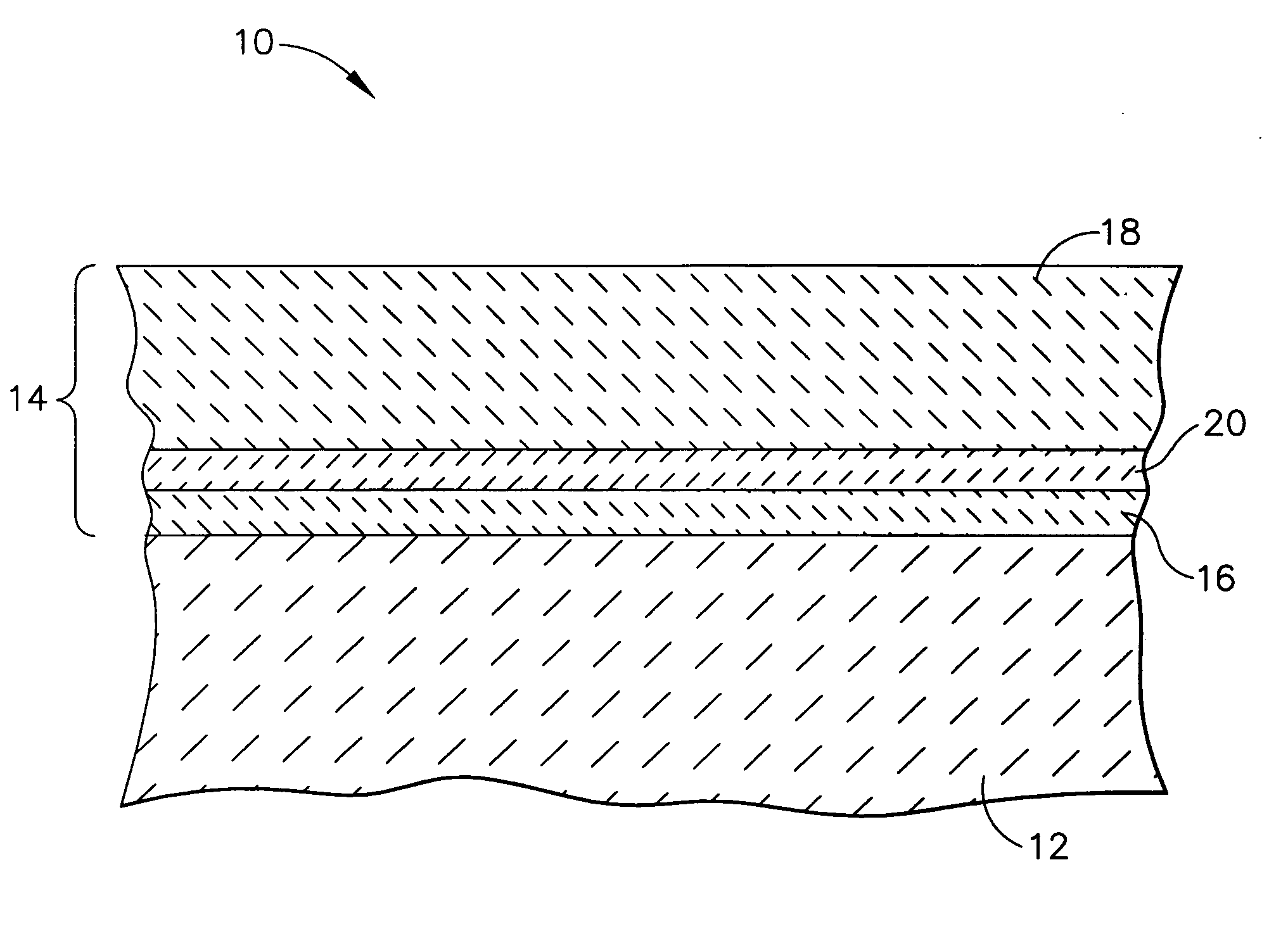
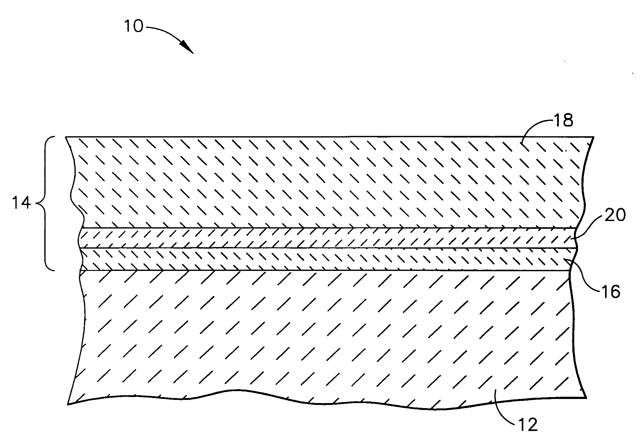
[0019] The present invention generally provides a coating system for a substrate formed of a silicon-comprising material, particularly for articles comprising such a substrate that are exposed to high temperatures, including the hostile thermal environment of a gas turbine engine. The substrate is typically formed of a material selected from the group consisting of silicon carbide; silicon nitride; composites having a matrix of at least one of silicon carbide, silicon nitride and silicon; and composites have at least one of a silicon carbide, silicon nitride and silicon matrix reinforced ...


PUM

PropertyMeasurementUnit
Lengthaaaaaaaaaa
Fractionaaaaaaaaaa
Fractionaaaaaaaaaa

Abstract

An article comprising a substrate formed of a silicon-comprising material, such as an article exposed to the hostile thermal environment of a gas turbine engine. The article further comprises an environmental barrier layer, e.g., an alkaline earth metal aluminosilicate, and a physical barrier layer overlying the environmental barrier layer. The physical barrier layer comprises zirconia or hafnia stabilized with an oxide of a metal selected from the group consisting of magnesium, calcium, scandium, yttrium, and lanthanide metals; and a low CTE oxide selected from the group consisting of niobia and tantala; and mixtures thereof. A method for preparing an environmental barrier coating system on a substrate formed of a silicon-comprising material is also disclosed.

Description


Claims


Application Information

Patent Timeline
Owner GENERAL ELECTRIC CO
Why Eureka
Try Eureka