Golf putter head with visual alignment system

Inactive Publication Date: 2006-07-27
SIENNA SPORT
View PDF31 Cites 96 Cited by
  • Summary
  • Abstract
  • Description
  • Claims
  • Application Information

AI Technical Summary

Benefits of technology

[0009] The present invention addresses the above-mentioned need in the art by providing a golf putter head having an iintuitive and inherently more simple and user-friendly alignment system than the series of marks, dots, lines, right angle markings, and the like used in the prior art. The golf putter head of the present invention improves alignment by incorporating a pipe component into the golf putter head that has a diameter intended to substantially correspond to the diameter of the golf ball, that is laterally centred on the striking face of the gold putter head, and has a pipe length along the swing axis of the striking face that allows the golfer to focus on the putt itself as opposed to a geometrically complicated series of indicia, each serving a different function. The pipe itself is a unitary alignment system that without a series of indicia, ball shapes, or angles provides all the visual information required to allow the user to understand quickly the orientation of the putter both at address and during the motion of the putting stroke.
[0010] The golf putter head of the invention also has an improved resistance to twisting o

Problems solved by technology

A less than perfect 3-dimensional alignment will result in the force applied to the golf ball not having the intended effect on the travel of the ball.
Many prior art golf putters address one or two alignment dimensions but few address all three alignment dimensions.
Those that do only do so to a very limited extent.
While this approach is beneficial to some extent, such golf putter head designs do not improve the opportunity for the golfer to align his club properly at address, takeaway the club properly on the backstroke, and keep the striking face square to the line on the forward stroke.
In fact, few putter designs adequately address the difficulty that the majority of golfers have in consistently delivering the sweet spot on the striking face of the golf putter squarely to the golf ball.
Unfortunately, many prior art putter head designs complicate the mental part of the putting process by complicating the align

Method used


Image

  • Golf putter head with visual alignment system
  • Golf putter head with visual alignment system
  • Golf putter head with visual alignment system

Examples


Embodiment Construction

[0021] A detailed description of exemplary embodiments of the present invention will now be described with reference to FIGS. 1-8. Although this description provides detailed examples of possible implementations of the present invention, it should be noted that these details are intended to be exemplary and in no way delimit the scope of the invention.

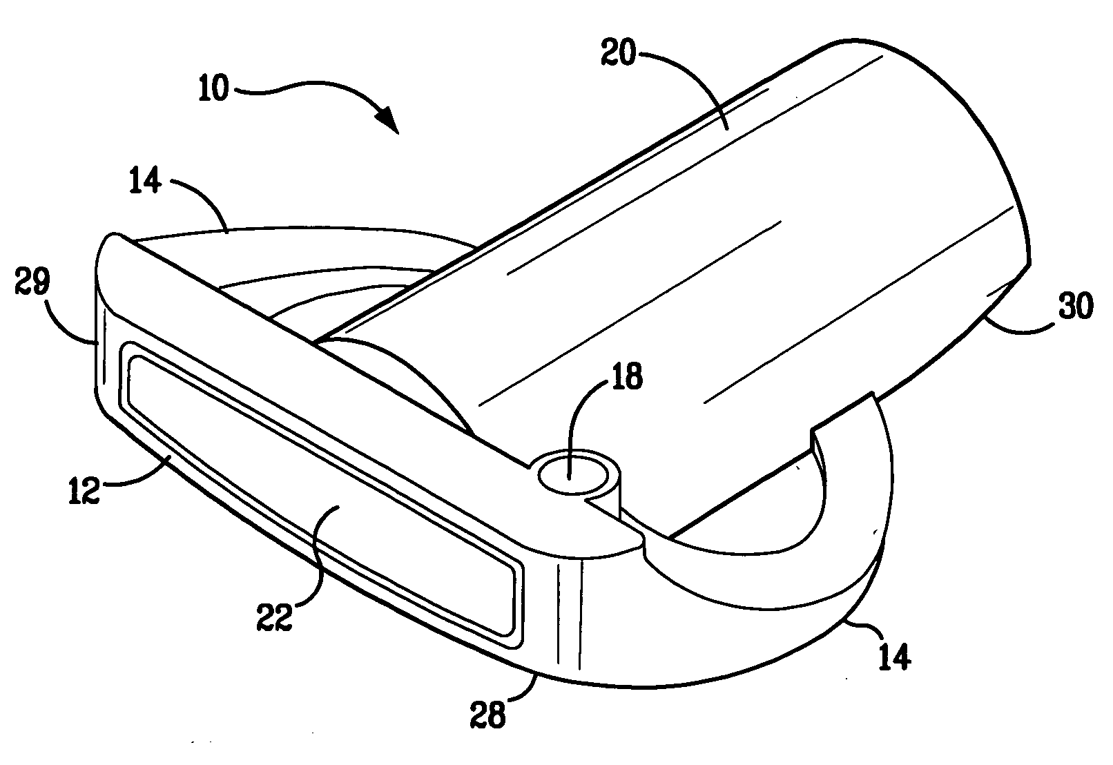
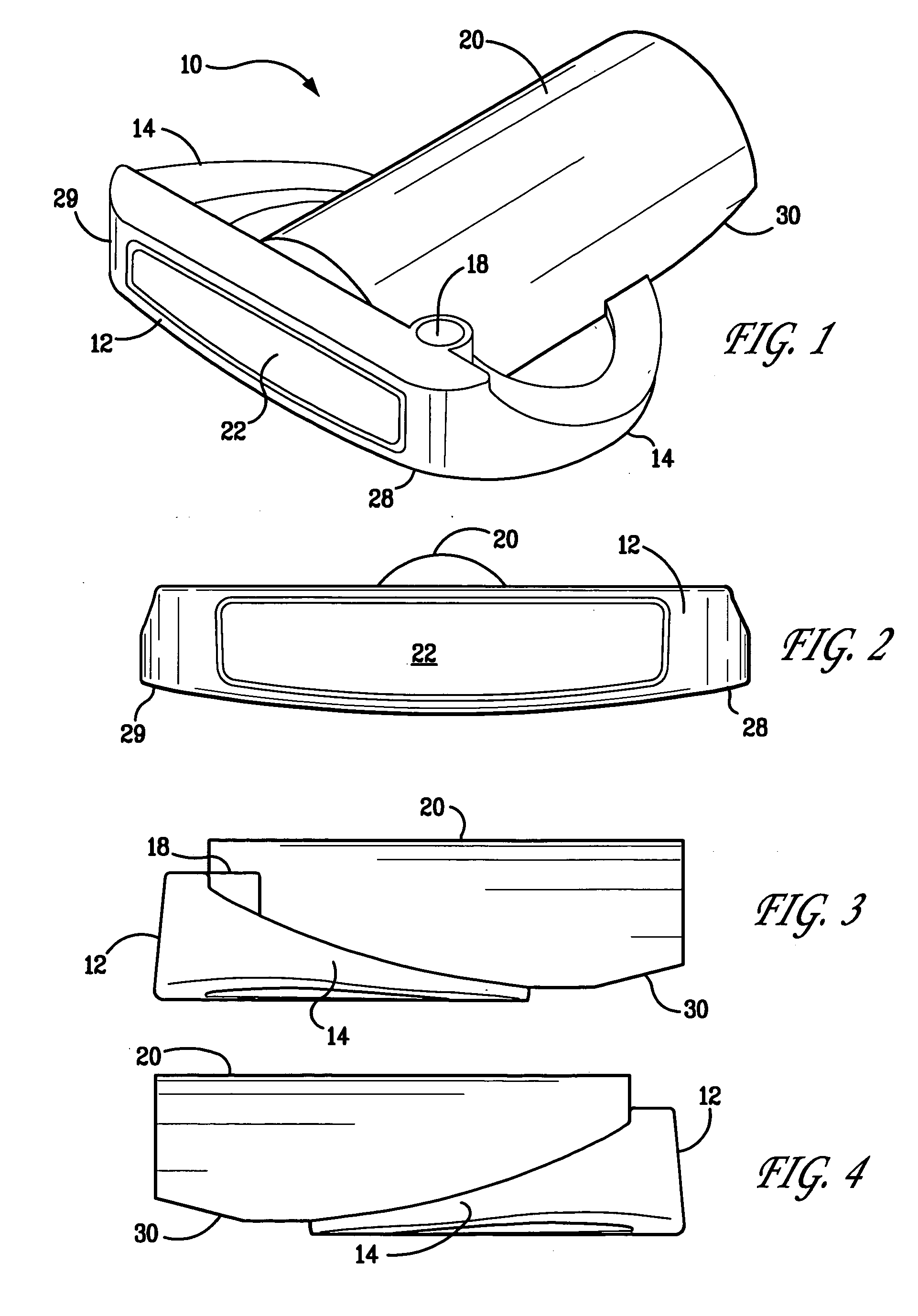
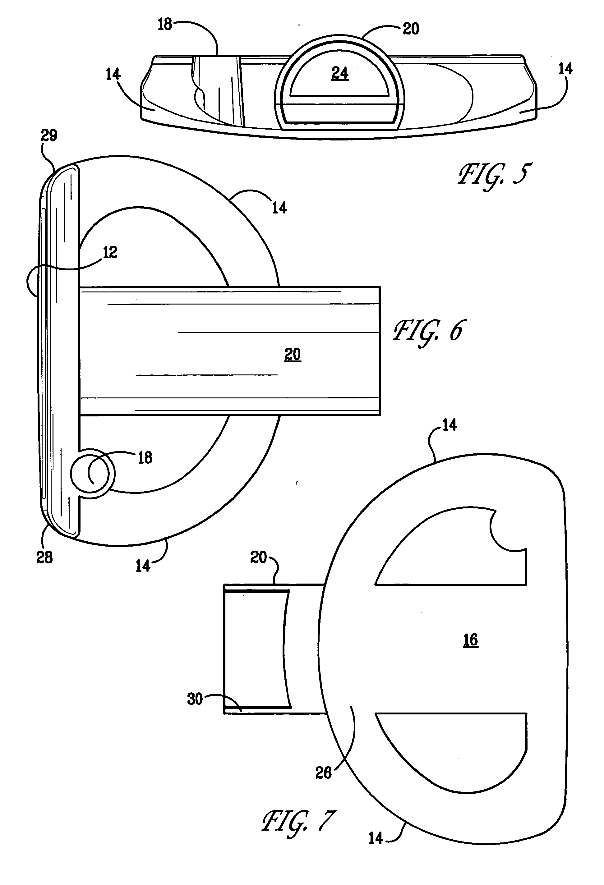
[0022]FIG. 1 illustrates a perspective view of a golf putter head 10 with a pipe alignment system in accordance with the invention. As illustrated, the golf putter head 10 includes a substantially planar strike face 12 that preferably includes a slight loft as best illustrated in the side views of FIGS. 3 and 4. The strike face 12 includes respective integral wings 14 that are also integrally formed with the support base 16 as best illustrated in FIG. 7. In an exemplary embodiment, the vertical height of the strike face 12 is approximately 1 inch, the thickness of the strike face 12 is approximately 0.3 inch to 0.4 inch, and the lengt...


PUM


Abstract

A mallet-style golf ball putter with a hollow pipe component that has generally the same diameter as a golf ball, is positioned about the sweet spot in the vertical and lateral dimensions on the putter striking face, and extends longitudinally towards the rear of the putter to assist the golfer to align the striking face of the putter with the golf ball when in an address position and with the intended line of putt during takeback and follow-through. Peripheral weighting further enhances the moment of inertia of the golf putter head. The pipe component so designed permits a visual alignment of the striking face with the golf ball in the lateral and vertical dimensions and for a smooth perpendicular stroke along an axis of the pipe.

Description

CROSS-REFERENCE TO RELATED APPLICATIONS [0001] The subject matter disclosed and claimed herein is related to the subject matter disclosed and claimed in U.S. Design patent application Ser. No. ______ (Attorney Docket No. SIEN-0003) filed on even date herewith.FIELD OF THE INVENTION [0002] The present invention relates to golf equipment and, more specifically, to a golf putter head having an alignment system that promotes a more consistent, repeatable golf stroke. BACKGROUND OF THE INVENTION [0003] Golf is a sport and a recreational activity that is a meant to be fun yet competitive. Perhaps the one area of the golf game that distresses and strikes fear and trepidation into many golfers is the art of putting, once defined as a “game within a game.” To achieve a successful outcome, the golfer is required to align the putter head in three distinct planes or dimensions. In particular, he is required to align the putter head on the intended line of his putting stroke such that, at impact...

Claims


Application Information

Patent Timeline
IPC IPC(8): A63B53/04A63B69/36
CPCA63B53/0487A63B59/0088A63B2053/0437A63B2053/0491A63B2053/0441A63B60/50A63B53/0437A63B53/0441A63B60/02
Inventor BROWN, JAMES P.
Owner SIENNA SPORT
Why Eureka
Try Eureka