Elliptical exercise machine with adjustable elliptical path

a technology of elliptical path and elliptical exercise machine, which is applied in the field of elliptical exercise machine, can solve the problems of overstressing of the knees of users and insufficient stroke length

Inactive Publication Date: 2006-07-27
JOHNSON TECH CO LTD
View PDF13 Cites 87 Cited by
  • Summary
  • Abstract
  • Description
  • Claims
  • Application Information

AI Technical Summary

Benefits of technology

[0007] An object of the present invention is to provide an elliptical exercise machine which permits foot plates to move along an elliptical path having a prolonged length along a front-to-rear direction without increasing the height of the elliptical path along a top-to-bottom direction.

Problems solved by technology

Thus, the length of the stroke may be insufficient for a user who is tall and requires a longer stroke, and may be unduly long for a user who is short and needs a smaller stroke to avoid overstressing his feet.
The increase in height of the elliptical path can result in overstressing of the knees of the user as the user must lift his knees too much when making an ascending movement.

Method used


Image

  • Elliptical exercise machine with adjustable elliptical path
  • Elliptical exercise machine with adjustable elliptical path
  • Elliptical exercise machine with adjustable elliptical path

Examples


first embodiment

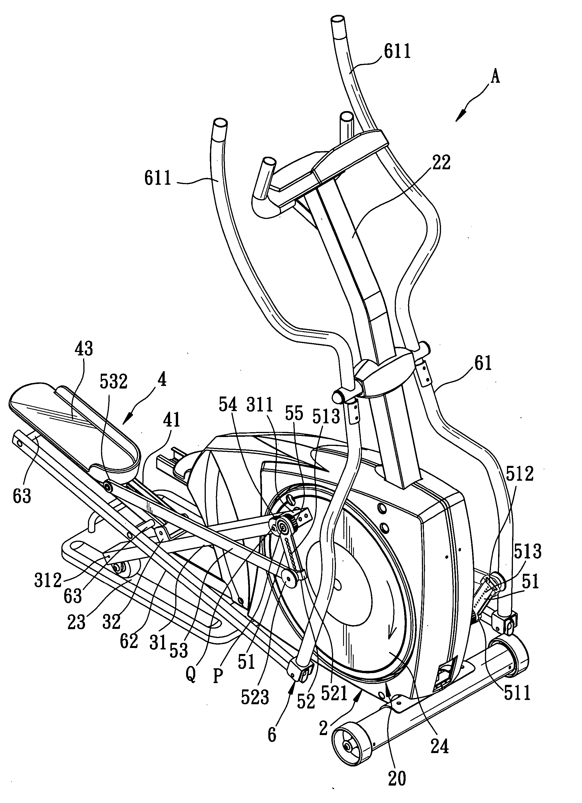
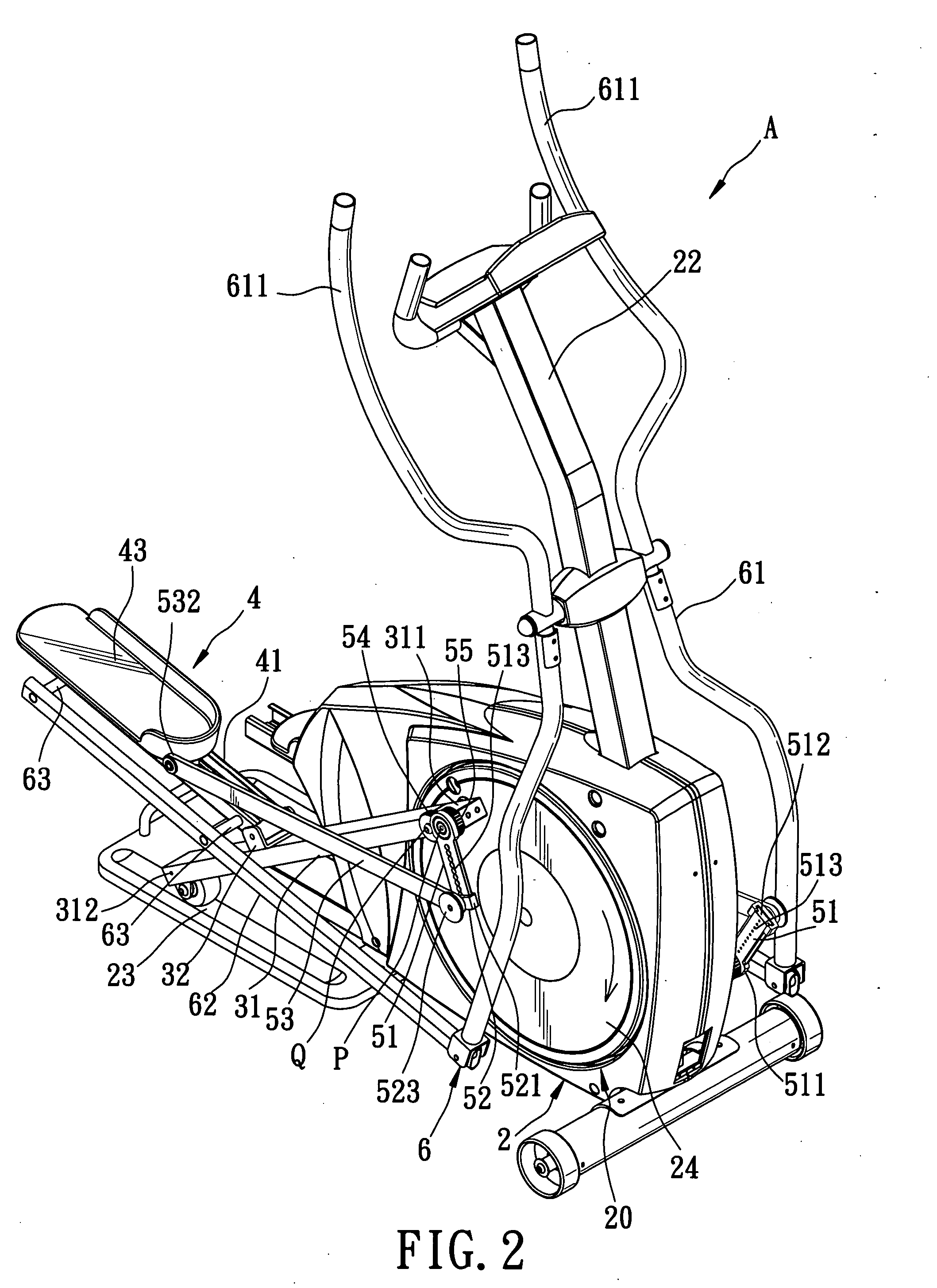
[0025] Referring to FIGS. 2 and 3, an exercise machine according to the present invention is shown at (A) which specifically designates an elliptical exercise machine. The elliptical exercise machine (A) comprises a support body 2 which includes a base 21, an upstanding frame 22 extending upward from a front end of the base 21, a pair of slide rails 23 provided in the base 21, and a rotating mechanism 20 mounted on the base 21 in front of the slide rails 23. The rotating mechanism 20 may be any rotating mechanism which is used conventionally in elliptical exercise machines. In this embodiment, the rotating mechanism 20 includes a flywheel 201 and a pair of rotary members 24 which are mounted coaxially on the base 21. While the rotary members 24 as shown are circular discs, the configuration of the rotary members 24 should not be limited thereto according to the present invention.

[0026] A pair of slide members 31 are mounted on the base 21 on two sides of the rotating mechanism 20. E...

second embodiment

[0038] Referring to FIGS. 12 and 13, the exercise machine according to the present invention is shown to include a support 2′, two slide members 31′, and two foot support members 4′. A rotary member 24′ is mounted on a rear part of a base 21′ of the support 2′ and is connected to the slide members 31′ having lower ends 312′ sliding on the base 21′.

[0039] Foot support seats 41′ of the foot support members 4′ are mounted fixedly on the respective slide members 31′ to support foot plates 43′, respectively. Each foot plate 43′ is slidable forward and rearward along rails 411′ provided on the corresponding foot support seat 41′. A pair of reciprocating members 64′ are connected respectively to the slide members 31′ and to two swinging arms 61′ that are in turn mounted on an upstanding frame 22′ of the support 2′.

[0040] Each foot plate 43′ is connected pivotally to a second arm 53 which in turn is pivoted to a first arm 51. The first arm 51 is connected pivotally to a pivotal end 311′ of...


PUM


Abstract

An exercise machine includes a pair of reciprocating slide members each having a pivotal end connected to a rotating mechanism and a sliding end slidable on a support. A foot plate 43 is mounted slidably on a corresponding slide member. A linkage unit is connected to each foot plate and the rotating mechanism, and a control mechanism is associated with the linkage unit and the foot plate for actuating the foot plate to move forward when the slide member moves forward and to move rearward when the slide member moves rearward. An elliptical path of the exercise machine can be enlarged due to the slidable foot plate and the control mechanism.

Description

BACKGROUND OF THE INVENTION [0001] 1. Field of the Invention [0002] This invention relates to an exercise machine, more particularly to an elliptical exercise machine which permits the user to exercise by moving his / her feet along an elliptical path. [0003] 2. Description of the Related Art [0004] Referring to FIG. 1, a typical elliptical exercise machine includes a frame 11 which carries a pair of swinging arms 16, a pair of foot members 14 connected to a rotating mechanism 12 through cranks 13, and a pair of reciprocating members 17 each of which is connected to one of the swinging arms 16. The foot members 14 are provided respectively with foot platforms 15. The bottom ends of the foot members 14 are slidable along rails provided on the frame 11. When the user stands on the foot platforms 15 and exercises by moving the foot platforms 15 with his feet, the foot members 14 move forward and rearward, and the cranks 13 rotate about the axis of the rotating mechanism 12 so that each f...

Claims


Application Information

Patent Timeline
Patent Type & Authority Applications(United States)
IPC IPC(8): A63B22/04A63B22/06
CPCA63B22/001A63B22/0015A63B22/0664A63B22/203A63B2022/067A63B2022/0676
Inventor LIAO, HUNG-MAOHUANG, TE-CHANG
Owner JOHNSON TECH CO LTD
Why Eureka
Try Eureka