Minimally invasive spinal fixation guide systems and methods

a spinal fixation and guide system technology, applied in the field of minimally invasive spinal fixation guide system and method, can solve the problems of significant damage to surrounding tissue and muscl

Active Publication Date: 2006-07-27
DEPUY SYNTHES PROD INC
View PDF35 Cites 169 Cited by
  • Summary
  • Abstract
  • Description
  • Claims
  • Application Information

AI Technical Summary

Benefits of technology

[0013] While the guide system can have a variety of configurations, in one embodiment the rod-engaging member is effective to maintain the rod in a fixed position that is spaced a distance apart from the guide portion and substantially parallel to the guide portion. The targeting member may be adapted to target an implant site on a vertebra that is at a location offset from the spinal rod. In other exemplary embodiments, the device can include a locking mechanism coupled to the rod-engaging member and effective to removably mate a spinal fixation rod to the rod-engaging member.

Problems solved by technology

While this procedure offers advantages over prior art invasive techniques, the transverse introduction of the rod can cause significant damage to surrounding tissue and muscle.

Method used


Image

  • Minimally invasive spinal fixation guide systems and methods
  • Minimally invasive spinal fixation guide systems and methods
  • Minimally invasive spinal fixation guide systems and methods

Examples


Embodiment Construction

[0035] Certain exemplary embodiments will now be described to provide an overall understanding of the principles of the structure, function, manufacture, and use of the devices and methods disclosed herein. One or more examples of these embodiments are illustrated in the accompanying drawings. Those skilled in the art will understand that the devices and methods specifically described herein and illustrated in the accompanying drawings are non-limiting exemplary embodiments and that the scope of the present invention is defined solely by the claims. The features illustrated or described in connection with one exemplary embodiment may be combined with the features of other embodiments. Such modifications and variations are intended to be included within the scope of the present invention.

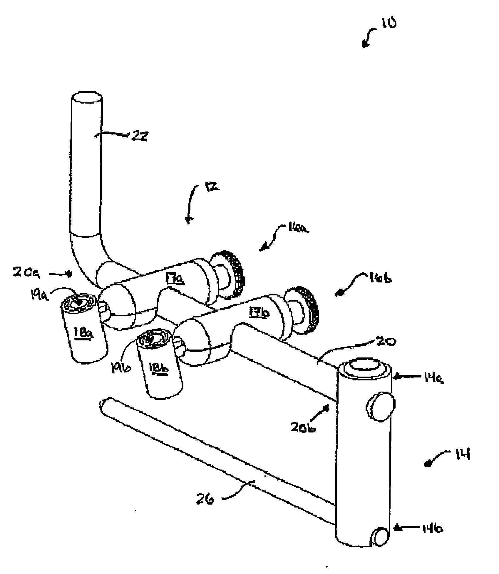
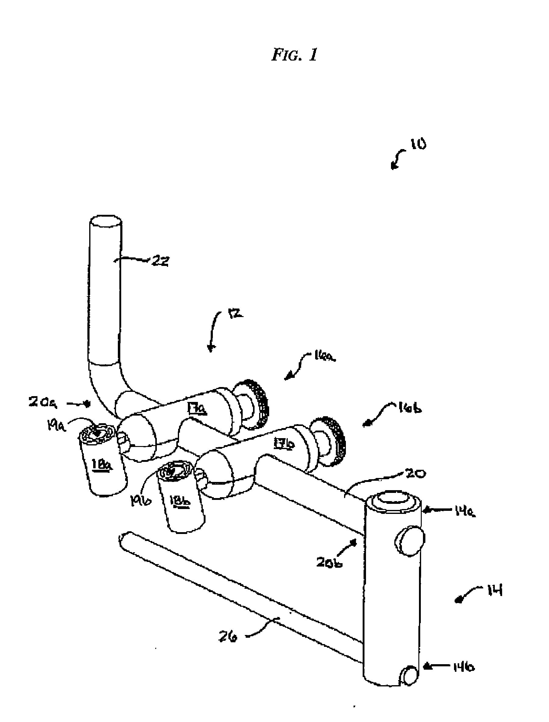
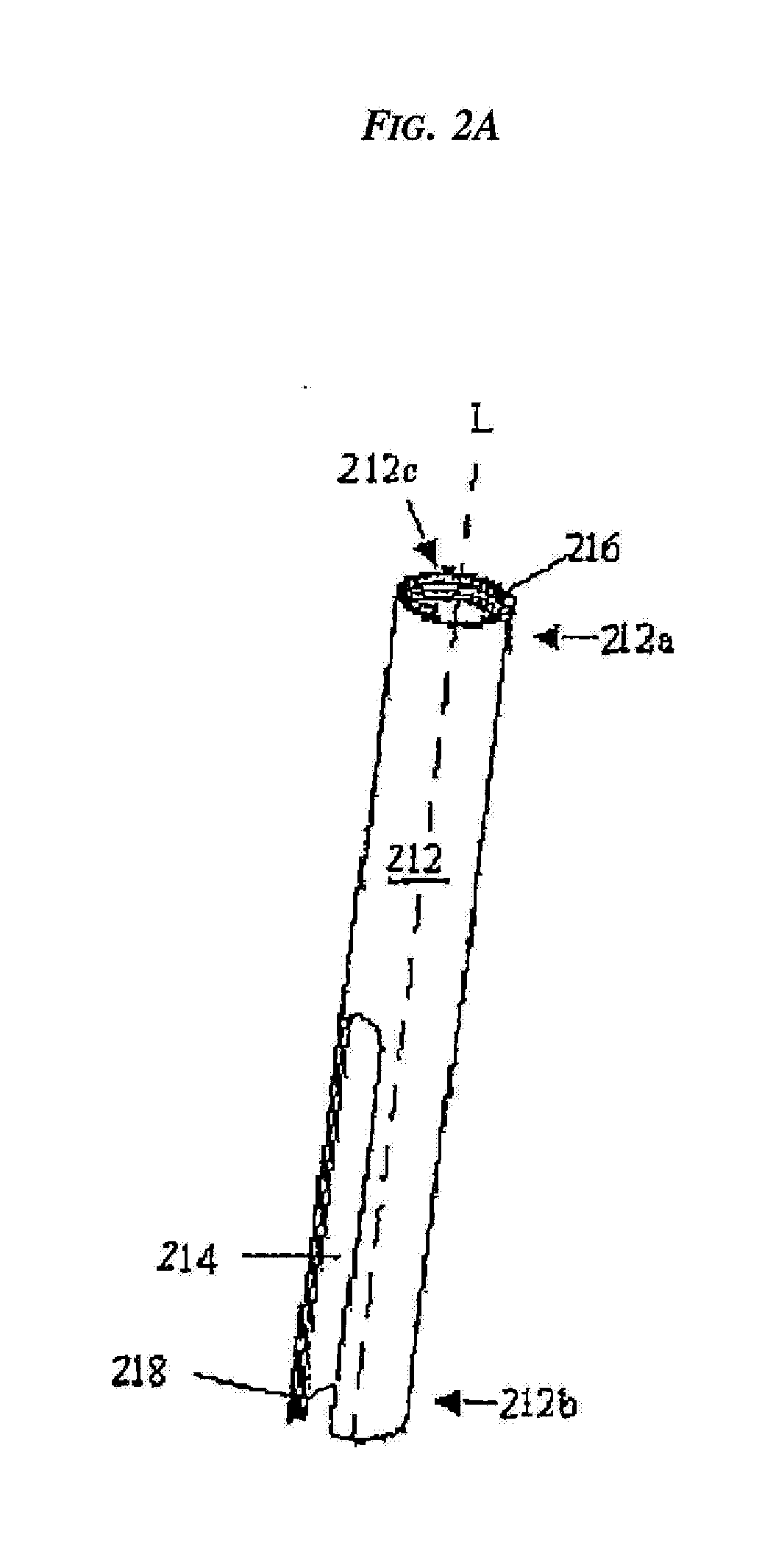
[0036] Disclosed herein are methods and devices for introducing spinal fixation elements, spinal anchors, and / or other spinal devices into a patient's spine. A person skilled in the art will appreci...


PUM


Abstract

Methods and devices for implanting spinal fixation implants and devices are provided. In one embodiment, a method for implanting a spinal fixation system is provided and it includes the steps of positioning a spinal fixation element to extend along a patient's spinal column adjacent to one or more vertebrae, determining an implant site on at least one vertebra, implanting at least one spinal anchor at the implant site on at least one vertebra, and coupling the spinal fixation element to each implant.

Description

CROSS REFERENCE TO RELATED APPLICATIONS [0001] This application claims priority to U.S. Provisional Patent Application No. 60 / 626,138 filed on Nov. 9, 2004 and entitled “Minimally Invasive Spinal Fixation Guide Systems and Methods,” which is hereby incorporated by reference in its entirety.BACKGROUND [0002] For a number of known reasons, spinal fixation devices are used in orthopedic surgery to align and / or fix a desired relationship between adjacent vertebral bodies. Such devices typically include a spinal fixation element, such as a relatively rigid fixation rod, that is coupled to adjacent vertebrae by attaching the element to various anchoring devices, such as hooks, bolts, wires, or screws. The fixation elements can have a predetermined contour that has been designed according to the properties of the target implantation site, and once installed, the instrument holds the vertebrae in a desired spatial relationship, either until desired healing or spinal fusion has taken place, ...

Claims


Application Information

Patent Timeline
Patent Type & Authority Applications(United States)
IPC IPC(8): A61F2/30
CPCA61B17/1735A61B17/1757A61B17/7034A61B17/7088
Inventor LUDWIG, STEVENANDERSON, DAVID GREGMICHIELLI, MICHAEL CARLCORMIER, PHILIPMILLER, NICHOLAS J.
Owner DEPUY SYNTHES PROD INC
Why Eureka
Try Eureka