Modular diaphyseal and collar implant

a diaphyseal and collar implant technology, applied in the field of prosthetic joints, can solve the problems of ligamentous instability, significant bone loss, and failure of primary prosthesis

Active Publication Date: 2006-07-27
DEPUY PROD INC
View PDF62 Cites 16 Cited by
  • Summary
  • Abstract
  • Description
  • Claims
  • Application Information

AI Technical Summary

Benefits of technology

[0016] In another aspect, the present invention addresses this need by providing an orthopaedic implant system for replacing a portion of a long bone. The long bone has an articulation portion, a diaphysis and an intramedullary canal. The kit includes a plurality of articulation components, a plurality of modular stems, a plurality of modular diaphyseal implant components, and a plurality of collar components. Each articulation component is shaped and sized to replace the articulation portion of the long bone, and includes a tapered bore having a first size. The modular stems are to be received in the intramedullary canal of the long bone. Each stem has a free end and an opposite end capable of being connected to another implant component. The modular diaphyseal implant components are capable of being connected to the modular stems. Each diaphyseal implant component includes a first end, a second end and a tapered outer surface. The first end has a tapered post and the second end is provided for connection to a selected modular stem. A longitudinal axis extends between the first end and the second end of each diaphyseal implant component. The tapered outer surface of each diaphyseal implant component has a minimum outer dimension at the second end and a maximum outer dimension positioned between the first end and the second end. Each collar component includes a first end having a post and a second end having a tapered bore co-axial with the post of the first end. The tapered bore of the collar component is smaller than the tapered bore of the articulation component. Each collar has a longitudinal axis extending from the first end to the second end. The longitudinal axis extends through the post at the first end and the bore on the second end. Each collar also has a substantially cylindrical portion between the first end and the second end. The substantially cylindrical portion surrounds at least a portion of the bore at the second end and includes an annular surface disposed transverse to the longitudinal axis of the diaphyseal implant component. The tapered post of each collar component is sized and shaped so that the each collar component can be assembled with each articulation component and frictionally locked together by inserting the tapered post of the collar into the tapered bore of the articulation component. The tapered post of each diaphyseal component is sized and shaped so that each diaphyseal component can be assembled with each collar component and frictionally locked together by inserting the tapered post of the diaphyseal component into the tapered bore of the collar component.
[0017] In another aspect, the present invention provides a method of replacing a portion of a long bone having an articulating surface, an intramedullary canal, a diaphysis spaced from the articulating surface, and a periosteum. A plurality of bone replacement components are provided; each bone replacement component is shaped and sized to replace a portion of the long bone, and each bone replacement component includes a tapered bore. A plurality of modular stems are also provided. The stems are to be received in the intramedullary canal of the long bone, and each stem has a free end and an opposite end capable of being connected to another implant component. A plurality of modular diaphyseal implant components are also provided. Each diaphyseal implant component includes a first end with a tapered post and a second end for connection to a selected modular stem. Each diaphyseal implant component also has a longitudinal axis extending between the first end and the second end and a tapered outer surface. The tapered outer surface has a minimum outer dimension at the second end and a maximum outer dimension positioned between the first end and the second end. At least two of the diaphyseal components have different maximum outer diameters. A plurality of collar components is also provided. Each collar component includes a first end having a post and a second end. The second end has a tapered bore co-axial with the post of the first end. The tapered bore of the collar component is smaller than the tapered bore of the bone replacement implant components. Each collar also has a longitudinal axis extending from the first end to the second end. The longitudinal axis extends through the post at the first end and the bore on the second end. A substantially cylindrical porous portion surrounds at least a portion of the bore at the second end. The cylindrical porous portion is between the first end and the second end. At least two of the collar components have different maximum outer diameters. In the method, the bone is resected to remove a portion of the bone and leave at least a portion of the diaphysis of the bone. A tapered bore is prepared in the diaphysis of the bone. One stem component, one diaphyseal component, one collar component and one bone replacement component are selected. An implant assembly is made by connecting the selected stem component to the second end of the selected diaphyseal component, inserting the tapered post of the selected diaphyseal component into the tapered bore of the selected collar component, and inserting the tapered post of the selected collar component into the tapered bore of the selected bone replacement component. The implant assembly is then implanted so that the stem component is received in the intramedullary canal, a substantial part of the diaphyseal component is received in the tapered bore in the diaphysis of the bone and the collar component is exposed outside of the bone.

Problems solved by technology

On occasion, the primary prosthesis fails.
Failure can result from many causes, including wear, aseptic loosening, osteolysis, ligamentous instability, arthrofibrosis and patellofemoral complications.
Any of these conditions or a combination thereof can lead to significant amounts of bone loss.
With bone ingrowth limited to the free end of the stem extension, there is stress shielding of the bone surrounding the remainder of the stem extension, and a long lever arm is created; both of these effects can lead to early loosening of the implant.
Additionally, when significant ingrowth does occur and the stem extension must subsequently be removed, the procedure can be difficult.

Method used


Image

  • Modular diaphyseal and collar implant
  • Modular diaphyseal and collar implant
  • Modular diaphyseal and collar implant

Examples


Embodiment Construction

[0041] A modular orthopaedic knee implant system incorporating the principles of the present invention is illustrated in the accompanying drawings. The illustrated modular orthopaedic knee implant system includes components of several existing orthopaedic knee implant systems, along with new components that provide the orthopaedic surgeon with greater flexibility in selecting the appropriate components to suit the needs of an individual patient. These patient needs can include factors such as individual anatomy and the condition of the native bone tissue.

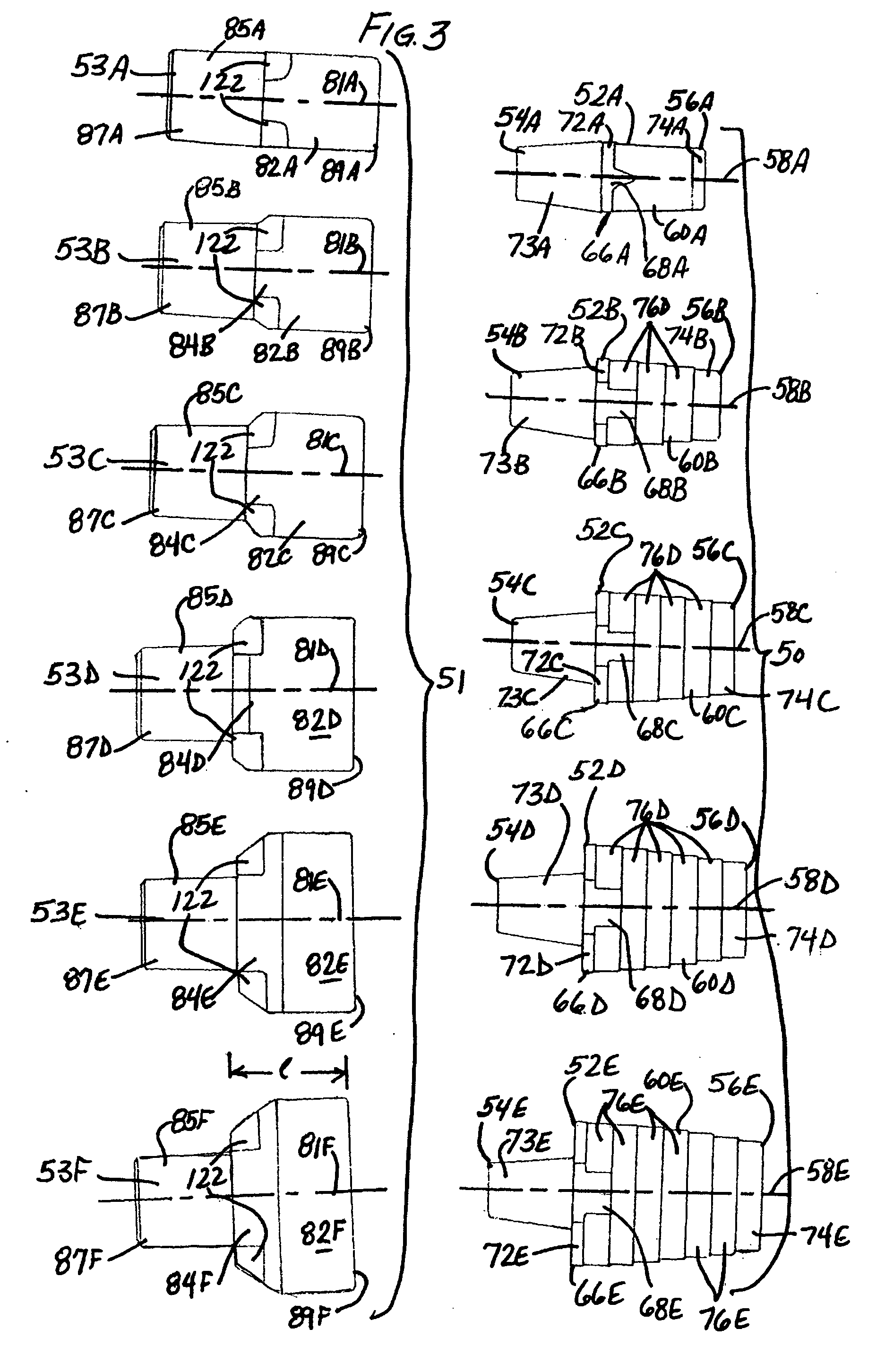
[0042]FIG. 3 illustrates a set 50 of diaphyseal components and a set of collar components 51 that may be used in the system or kit of the present invention. The illustrated set 50 of diaphyseal components includes five sizes of diaphyseal components, labeled 52A, 52B, 52C, 52D, 52E. The illustrated set of collar components 51 includes six sizes of collar components, labeled 53A, 53B, 53C, 53D, 53E, 53F.

[0043] The illustrated diaph...


PUM


Abstract

A modular implant system includes a set of anatomically-designed diaphyseal fitting and filling modular implant components and collars. The diaphyseal component connects with a selected intramedullary stem and with a selected collar component. The collar component connects to another implant component such as a modular articular component, a segmental component or an intercalary component. The diaphyseal component has a tapered porous surface that is received with a tapered bore in the bone diaphysis that is prepared to match the size and shape of the tapered porous surface. The collar component has a porous surface for tissue ingrowth, such as the periosteum, to seal the intramedullary canal. The diaphyseal implant is easy to insert and remove, does not bind before fully seating to prevent stress shielding, and eliminates the long lever arm created when fixation occurs only at the tip of the stem, and should eliminate related stem loosening.

Description

CROSS-REFERNCE TO RELATED APPLICATIONS [0001] The present invention claims priority to U.S. Provisional Patent Application Ser. No. 60 / 637,015, filed on Dec. 17, 2004 by Robert K. Heck and Stephen A. Hazebrouck and entitled “Modular Implant System and Method with Diaphyseal Implant,” U.S. Provisional Patent Application Ser. No. 60 / 731,999, filed on Oct. 31, 2005 by Robert K. Heck and Stephen A. Hazebrouck, and entitled “Modular Diaphyseal and Collar Implant,” and U.S. Provisional Patent Application Ser. No. 60 / 732,402, filed on Oct. 31, 2005 by Robert K. Heck and Stephen A. Hazebrouck and entitled “Modular Implant System and Method with Diaphyseal Implant and Adapter,” all of which are incorporated by reference herein in their entireties.BACKGROUND OF THE INVENTION [0002] The present invention relates generally to prosthetic joints and, more particularly, to modular orthopaedic lower extremity implant systems. [0003] The knee joint basically consists of the bone interface of the dis...

Claims


Application Information

Patent Timeline
Patent Type & Authority Applications(United States)
IPC IPC(8): A61F2/38
CPCA61F2/28A61F2/30721A61F2/30767A61F2/30942A61F2/36A61F2/367A61F2/3672A61F2/3676A61F2/38A61F2/384A61F2/3859A61F2/389A61F2/4684A61F2002/2825A61F2002/30233A61F2002/30329A61F2002/30332A61F2002/30344A61F2002/30367A61F2002/30382A61F2002/30405A61F2002/30594A61F2002/30599A61F2002/30604A61F2002/30616A61F2002/30774A61F2002/30827A61F2002/30878A61F2002/30886A61F2002/30925A61F2002/30968A61F2002/3611A61F2002/3625A61F2002/3674A61F2002/4631A61F2220/0025A61F2220/0033A61F2230/0069A61F2250/0063A61F2310/00023A61F2310/00029A61F2310/00796A61F2002/30331A61F2002/30339
Inventor HECK, ROBERT K.HAZEBROUCK, STEPHEN A.
Owner DEPUY PROD INC
Why Eureka
Try Eureka