Segmental prosthesis for human body long bone diaphysis position

A segmental, prosthesis technology, applied in the field of artificial prosthesis, can solve the problems of easy loosening, increased complications, and high cost, and achieves the effects of convenient installation, good stability, and not easy to loosen.

Inactive Publication Date: 2013-01-02
THYTEC SHANGHAI
View PDF7 Cites 11 Cited by
  • Summary
  • Abstract
  • Description
  • Claims
  • Application Information

AI Technical Summary

Problems solved by technology

[0004] (1) Allograft bone + compression plate fixation, Enneking followed up a large number of allograft bone transplant patients and found that the bone graft-bone bed junction healed slowly, and the local callus incorporation depth was 3-4mm for more than 10 years after transplantation , In addition, the amount of domestic allogeneic bone banks is small, which cannot meet the needs of patients at any time;
[0005] (2) Bone cement-filled intramedullary nail fixation method, according to Zhang Qing, Cai Qianbai, Niu Xiaohui and other long bone bone metastases surgery follow-up analysis report (Chinese Journal of Surgery (2003, 41 (2): 134-138), due to bone cement and marrow The physical and chemical properties of the inner needle are quite different, which leads to the detachment of the bone cement and the intramedullary nail under long-term load-bearing conditions, causing the displacement of the intramedullary nail, resulting in more complications;
Therefore, the existing segmental tumor prostheses have the following disadvantages: (1) they need to be customized, the cost is high, and they cannot quickly meet the needs of patients; The proximal tumor prosthesis grooves are matched, so the prosthesis installation is not very convenient; (3) During the normal life of the patient, the screws are easily loosened or even broken under complex stress conditions, posing safety hazards

Method used


Image

  • Segmental prosthesis for human body long bone diaphysis position
  • Segmental prosthesis for human body long bone diaphysis position
  • Segmental prosthesis for human body long bone diaphysis position

Examples


Embodiment 1

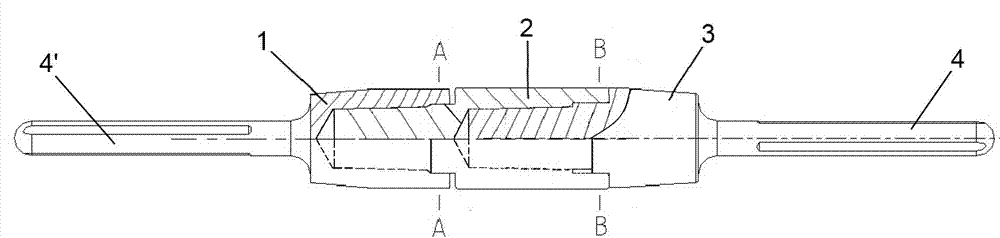
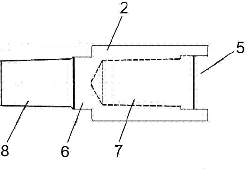
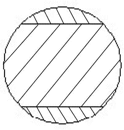
[0021] figure 1 It is one of the structural schematic diagrams of the three-stage assembled segmental prosthesis of the present invention; figure 2 for figure 1 Schematic diagram of the middle prosthesis structure; image 3 with Figure 4 respectively figure 1 Schematic diagram of the A-A and B-B cross-sectional structures in . Such as Figure 1 ~ Figure 4 As shown, a segmental prosthesis for the diaphysis of human long bones, including a first tumor prosthesis 1 and a second tumor prosthesis 3, is characterized in that: one end of the first tumor prosthesis 1 is placed with an intramedullary The prosthesis handle 4' is provided with a blind hole 7 with a slot 5 at the other end; the second tumor prosthesis 3 is provided with an intramedullary prosthesis handle 4 at one end 7 and a socket with a bayonet 6 at the other end. A conical pin 8; a middle prosthesis 2 is placed between the first tumor prosthesis 1 and the second tumor prosthesis 3, a conical pin 8 with a bayon...

Embodiment 2

[0023] The two ends of the middle prosthesis 2 are respectively provided with blind holes 7 with card slots 5, and one end of the first tumor prosthesis 1 and the second tumor prosthesis 3 is respectively provided with a conical pin with a bayonet 6 8. Between the first tumor prosthesis 1 and the middle prosthesis 2, and between the middle prosthesis 2 and the second tumor prosthesis 3, by placing the first tumor prosthesis 1 and the second tumor prosthesis The conical pin 8 with the bayonet socket 6 of the body 3 is inserted into the blind hole 7 at the two ends of the middle prosthesis 2 respectively, the inner conical of the blind hole 7 and the outer conical taper of the conical pin 8 The matching is consistent, and the bayonet socket 6 and the bayonet slot 5 are embedded into each other to form a whole.

Embodiment 3

[0025] The two ends of the middle prosthesis 2 are respectively provided with conical pins 8 with bayonet sockets 6, and one end of the first tumor prosthesis 1 and the second tumor prosthesis 3 is respectively provided with a blind hole with a card slot 5 7. The connection between the first tumor prosthesis 1 and the mid-section prosthesis 2, and between the mid-section prosthesis 2 and the second tumor prosthesis 3, through two ends of the mid-section prosthesis 2 The conical pins 8 are respectively inserted into the blind holes 7 of the first tumor prosthesis 1 and the second tumor prosthesis 3, the outer cone of the conical pin 8 matches the inner cone taper of the blind hole 7, The bayonet socket 6 and the bayonet slot 5 are embedded into each other to form a whole.


PUM


Abstract

The invention relates to a segmental prosthesis for a human body long bone diaphysis position and belongs to the technical field of prosthesises. In order to solve the technical problem of fast responding to the patient requirements, the segmental prosthesis with good stability and installation convenience is provided. The segmental prosthesis is characterized in that one end of a first tumor prosthesis and one end of a second tumor prosthesis are respectively provided with an intramedullary prosthesis handle, the other end of the first tumor prosthesis and the other end of the second tumor prosthesis are respectively provided with a blind hole with a clamp groove and / or a conical pin with a bayonet, the mutual connecting parts of the first and second tumor prosthesises are placed into the blind holes through the conical pins to realize the insertion connection, the conicity of internal cones passing by the blind holes is matched and anastomotic with the conicity of external cones of the conical pins, the bayonets and the clamp grooves are mutually embedded and connected into a whole, a middle segment prosthesis can be also added between the first tumor prosthesis and the second tumor prosthesis, and the three-segment connection is realized by the same method of inserting the conical pins into the blind holes. The segmental prosthesis has the advantages that the middle segment prosthesis can be prefabricated into different specification for standby use, the structure is simple, the installation is convenient, the stability is good, and the looseness due to long-term stress cannot easily occur.

Description

technical field [0001] The invention belongs to the technical field of artificial prostheses, and relates to a segmental prosthesis for the diaphysis of human long bones. Background technique [0002] Malignant bone tumors of the human long bone diaphysis have seriously affected the quality of life of patients. The current surgical treatment goals mainly include: (1) pain relief; (2) reconstruction of limb function, allowing patients to restore weight-bearing function in a short time; (3) to facilitate future radiotherapy, Nursing for chemotherapy and daily life, and recovery of self-care ability. [0003] Limb-salvage surgery has become the main treatment for malignant bone tumors of the human long bone, and bone reconstruction after resection of the tumor is the main problem faced by limb-salvage surgery. At present, there are three options for clinically realizing the reconstruction of patients' limb functions: [0004] (1) Allograft bone + compression plate fixation, E...

Claims


Application Information

Patent Timeline
Patent Type & Authority Applications(China)
IPC IPC(8): A61F2/28
Inventor 郝永强戴尅戎
Owner THYTEC SHANGHAI
Why Eureka
Try Eureka