Data transmission device and data transmission system

a data transmission system and data transmission technology, applied in the field of data transmission apparatus and data transmission system, can solve the problems of increased processing load, high cost of communication equipment, and high cost of network construction

Inactive Publication Date: 2006-07-27
NIPPON TELEGRAPH & TELEPHONE CORP
View PDF10 Cites 17 Cited by
  • Summary
  • Abstract
  • Description
  • Claims
  • Application Information

AI Technical Summary

Benefits of technology

[0011] In order to solve the problems of the conventional technology described above, it is an object of the present invention to provide a data transfer apparatus, a data transfer system, a router apparatus, and a network system that allow a reduction in the network cost.
[0012] More concretely, it is an object of the present invention to provide a data transfer apparatus and a data transfer system that reduce the cost of installing in one exchange office communication equipment that is compatible with each of the various dissimilar communication protocols and reduce the cost for constructing the network.
[0013] In addition, it is an object of the present invention to provide a router apparatus and network system that raise the packet transfer efficiency by reducing the processing load, reducing the cost of the router apparatus, and thereby reduces the cost for constructing the network system, by affixing switching tags to packets in the transfer path order and switching the packets within the router apparatuses in sequence according to the switching tags.

Problems solved by technology

However, currently there is the problem that a high cost for communication equipment is incurred when placing in one exchange office the communication equipment that is compatible with each of the different communication protocols related to the tunneling technologies for transferring data efficiently in accordance with the various services that provide rapidly spreading VPN (virtual private network) and VLAN (virtual local area network) and the like.
Because large-scale networks are constructed by using only the high cost conventional data transfer apparatuses described above, there is the problem that the costs incurred to construct the network are high.
This switching tag also requires searching by the destination address or the label, and thus there is the problem that the processing load increases.
In addition, the cost of the router device increases due to the increase in the processing load, and thus there is also the problem that the cost of constructing the network becomes high.

Method used


Image

  • Data transmission device and data transmission system
  • Data transmission device and data transmission system
  • Data transmission device and data transmission system

Examples


first embodiment

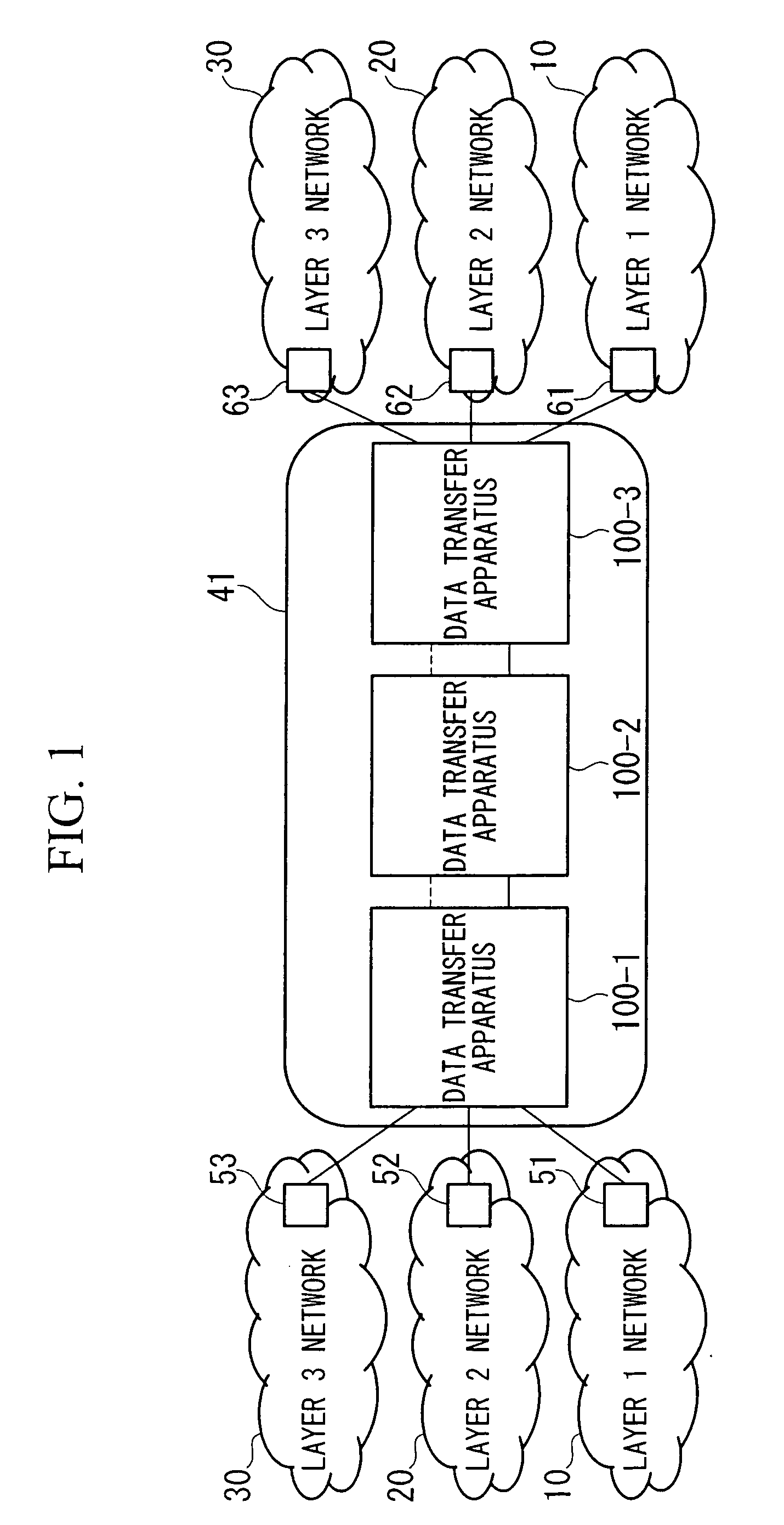
[0065]FIG. 1 is a block diagram showing the system structure of the data transfer system of the first embodiment of the present invention.

[0066] As shown in FIG. 1, although the data transfer system 41 of the present embodiment is formed so as to include a plurality of data transfer apparatuses 100, the data transfer device 41 can be formed by only one data transfer apparatus 100. In addition, the data transfer system 41 can form a backbone network, and the backbone network connects to external networks including a layer 1 network 10, a layer 2 network 20, and a layer 3 network 30.

[0067] The layer 1 network 10 is formed so as to include the upstream data transfer apparatus 51 and the downstream data transfer apparatus 61.

[0068] Note that the term “upstream data transfer apparatus” denotes a data transfer apparatus that transmits received data when viewed from the data transfer apparatus that receives data. The term “downstream data transfer apparatus” denotes the data transfer ap...

second embodiment

[0131]FIG. 4 is a block diagram showing the system configuration for the data transfer system according to the second embodiment of the present invention.

[0132] As shown in FIG. 4, the data transfer system 42 of the present embodiment is formed so as to include a plurality of data transfer apparatuses 100 and a data transfer apparatus 200. However, the data transfer system 42 can be formed by one data transfer apparatus 200 or can be formed by a data transfer apparatus 200 and other data transfer apparatuses. In addition, the data transfer system 42 can form a backbone network, and the backbone network is connected to an external network including a layer 1 network 10, a layer 2 network 20, and a layer 3 network 30.

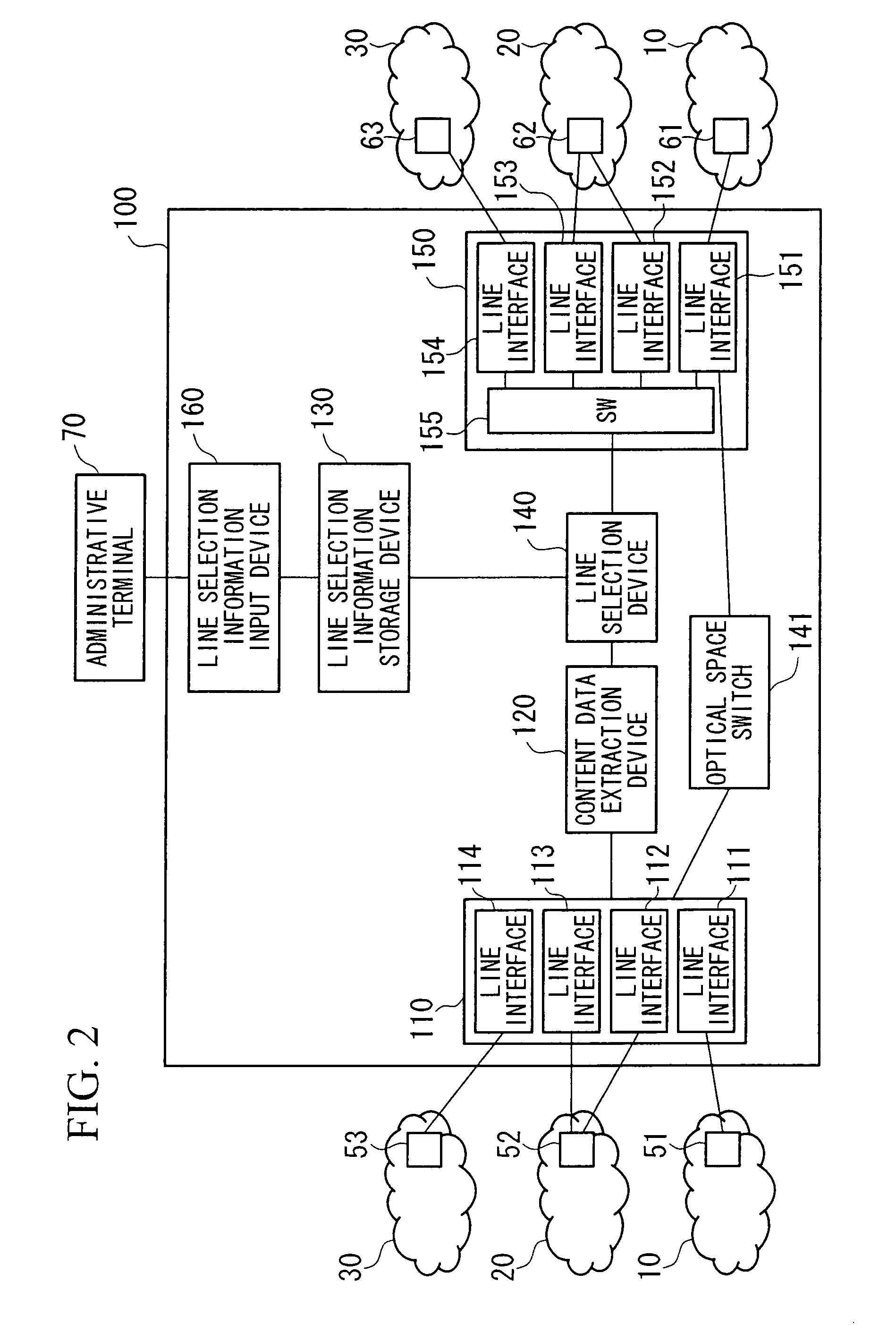
[0133]FIG. 5 is a block diagram showing the schematic structure of the data transfer apparatus according to the second embodiment of the present invention.

[0134] As shown in FIG. 5, the data transfer apparatus 200 of the present embodiment including a data reception de...

third embodiment

[0156]FIG. 7 is a block diagram showing the system structure of the data transfer system according to the third embodiment of the present invention.

[0157] As shown in FIG. 7, the data transfer system 43 of the present embodiment is formed so as to include a plurality of data transfer apparatuses 100 and a data transfer apparatus 300. However, the data transfer system 43 can be formed by one data transfer apparatus 300, or can be formed by a data transfer apparatus 300 and other data transfer apparatuses. In addition, the data transfer system 43 can form a backbone network, and the backbone network can be connected to an external network including a layer 1 network 10, a layer 2 network 20, and a layer 3 network 30.

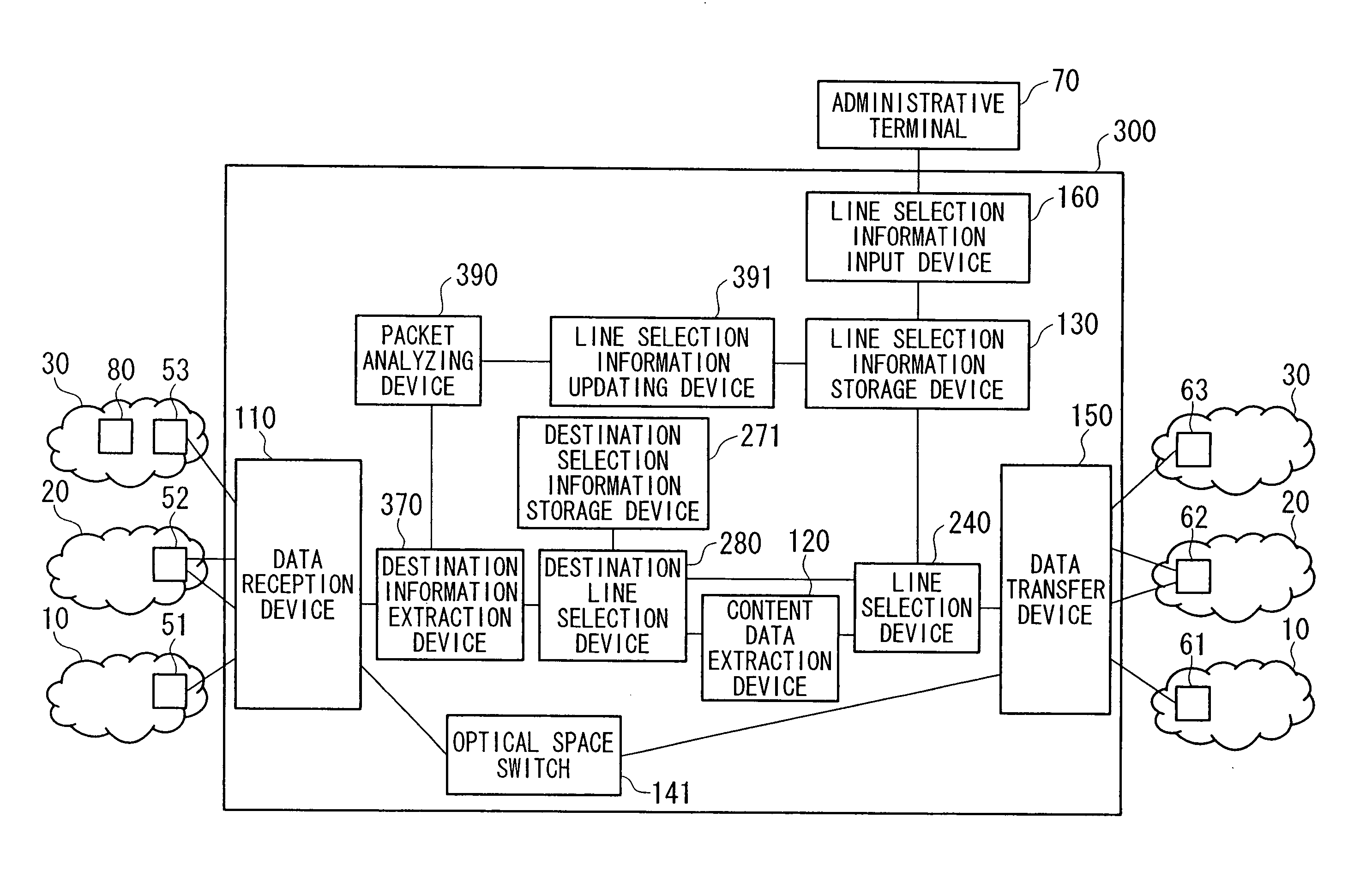
[0158]FIG. 8 is a block diagram showing a schematic structure of the data transfer apparatus according to the third embodiment of the present invention.

[0159] As shown in FIG. 8, the data transfer apparatus 300 of the present embodiment including a data reception device...


PUM


Abstract

A data transfer apparatus and a data transfer system are provided that can reduce the cost of installing communication equipment compatible with each of several dissimilar communication protocols in one exchange office and can reduce the cost of constructing the network. The data transfer apparatus includes a data reception device (110) that receives packets that comply with dissimilar communication protocols from upstream data transfer apparatuses (51, 52, and 53); a content data extraction device (120) that extracts content data included in the packets; a line selection information storage device (130) that stores the line selection information for selecting communication lines that comply with dissimilar communication protocols; a line selection device (140) that selects the communication line compatible with content data based on the line selection information; and a data transfer device (150) that transfers data to downstream data transfer apparatuses (61, 62, and 63) that are connected to the communication line that has been selected by the line selection device.

Description

TECHNICAL FIELD [0001] The present invention relates to a data transfer apparatus and data transfer system that transfer data, and in particular relates to a data transfer apparatus and a data transfer system that comply with the communication protocols that relate to networks. In addition, the present invention relates in particular to apparatuses (below referred to as router apparatuses) and network systems in which the switching of packets (below, referred to as IP packets) among data transfer apparatuses is carried out in compliance with Internet Protocol, and, when the network is constructed by a plurality of router apparatuses, relates to an advantageous technology that is applied to these router apparatuses. BACKGROUND ART [0002] As an example of a conventional data transfer apparatus, a data transfer apparatus positioned at the edge of a network is known that allocates a different light wavelength for each destination address contained in the IP packet, time division multipl...

Claims


Application Information

Patent Timeline
Patent Type & Authority Applications(United States)
IPC IPC(8): G06F15/173H04L45/60H04L69/14
CPCH04L12/4666H04L12/4675H04L69/18
Inventor KABASHIMA, KEISUKEAOKI, MICHIHIROKURIMOTO, TAKASHIMIYAMURA, TAKASHIGOSHIMA, MASAHIROMATSUURA, NOBUAKIURUSHIDANI, SHIGEO
Owner NIPPON TELEGRAPH & TELEPHONE CORP
Why Eureka
Try Eureka