Re-challenge communication control method and system thereof, packet transfer enabled/disabled decision method, packet transfer device, packer transfer system, packet monitoring method, call control device, monitor device, and program

a communication control and communication control technology, applied in the field of retry communication control methods and systems, can solve problems such as deterioration of test packets, overflow of trial packets, and decrease of total throughput, and achieve the effect of improving the monitoring efficiency of the monitor apparatus

Inactive Publication Date: 2006-07-27
NIPPON TELEGRAPH & TELEPHONE CORP
View PDF5 Cites 66 Cited by
  • Summary
  • Abstract
  • Description
  • Claims
  • Application Information

AI Technical Summary

Benefits of technology

[0133] This embodiment is applied to a terminal-initiative communication system that estimates a communication possibility with the use of test packets. The...

Problems solved by technology

This produces an overflow of trial packets in an overload state and decreases a total throughput.
If the requested new flow is of over 5 Mbps, the test packets deteriorate during transmission and the sender terminal receives a faulty result from the receiver terminal.
This affects all of the flows, to drastically decrease the throughput of a communication network as a whole.
This technique of stabilizing the traffic of a whole network, however, greatly increases the number of test packets in each flow.
In addition, the technique frequently fails to establish new flows, in particular, in access sections involving narrow bands.
This technique, therefore, is inefficient.
This, however, extends a time to determine the possibility of establishing a flow, and therefore, deteriorates serviceability.
In this case, discarding a specific flow is impossible to carry out unless information on each flow is stored in routers.
If the new communication path is in use by ...

Method used


Image

  • Re-challenge communication control method and system thereof, packet transfer enabled/disabled decision method, packet transfer device, packer transfer system, packet monitoring method, call control device, monitor device, and program
  • Re-challenge communication control method and system thereof, packet transfer enabled/disabled decision method, packet transfer device, packer transfer system, packet monitoring method, call control device, monitor device, and program
  • Re-challenge communication control method and system thereof, packet transfer enabled/disabled decision method, packet transfer device, packer transfer system, packet monitoring method, call control device, monitor device, and program

Examples


first embodiment

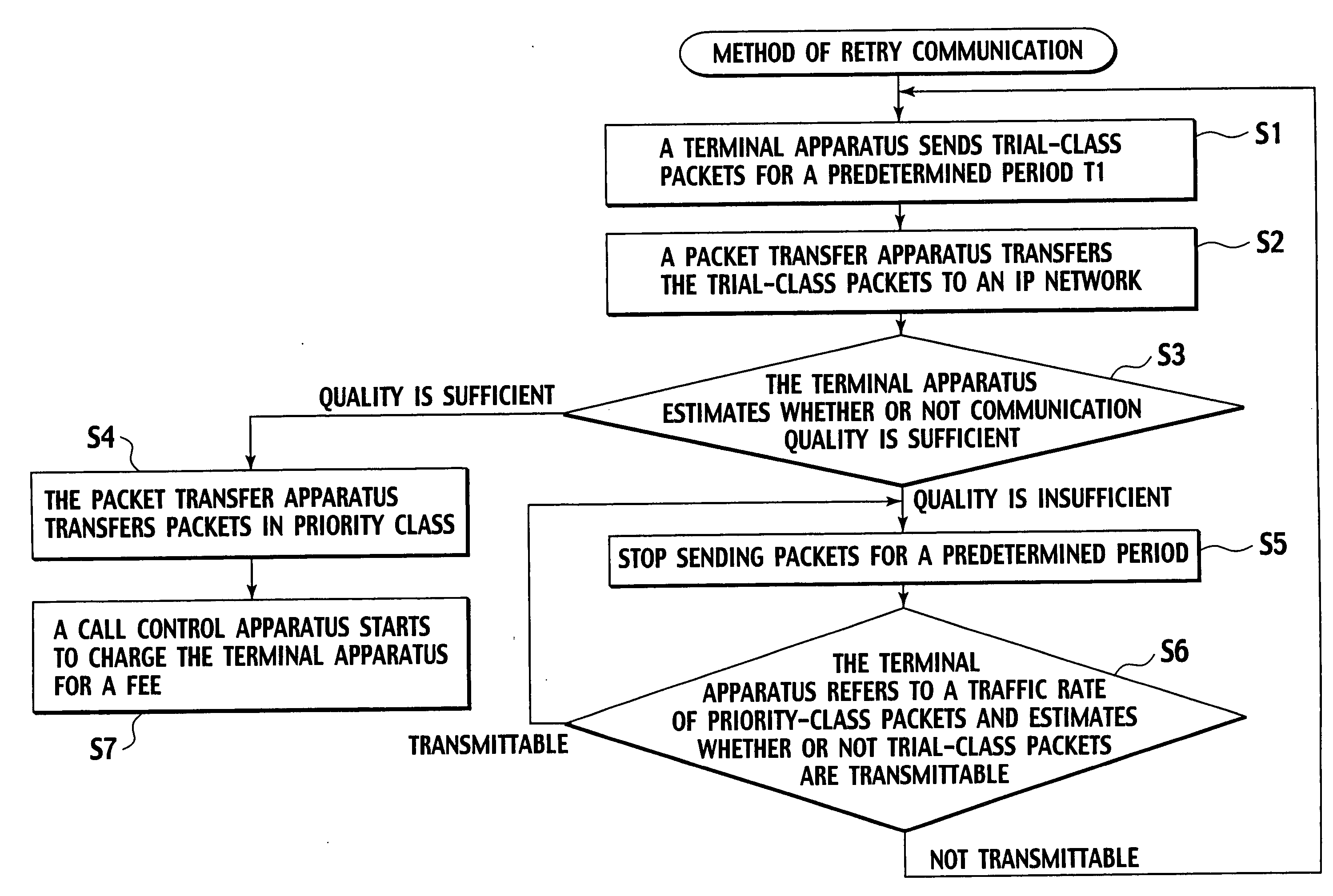
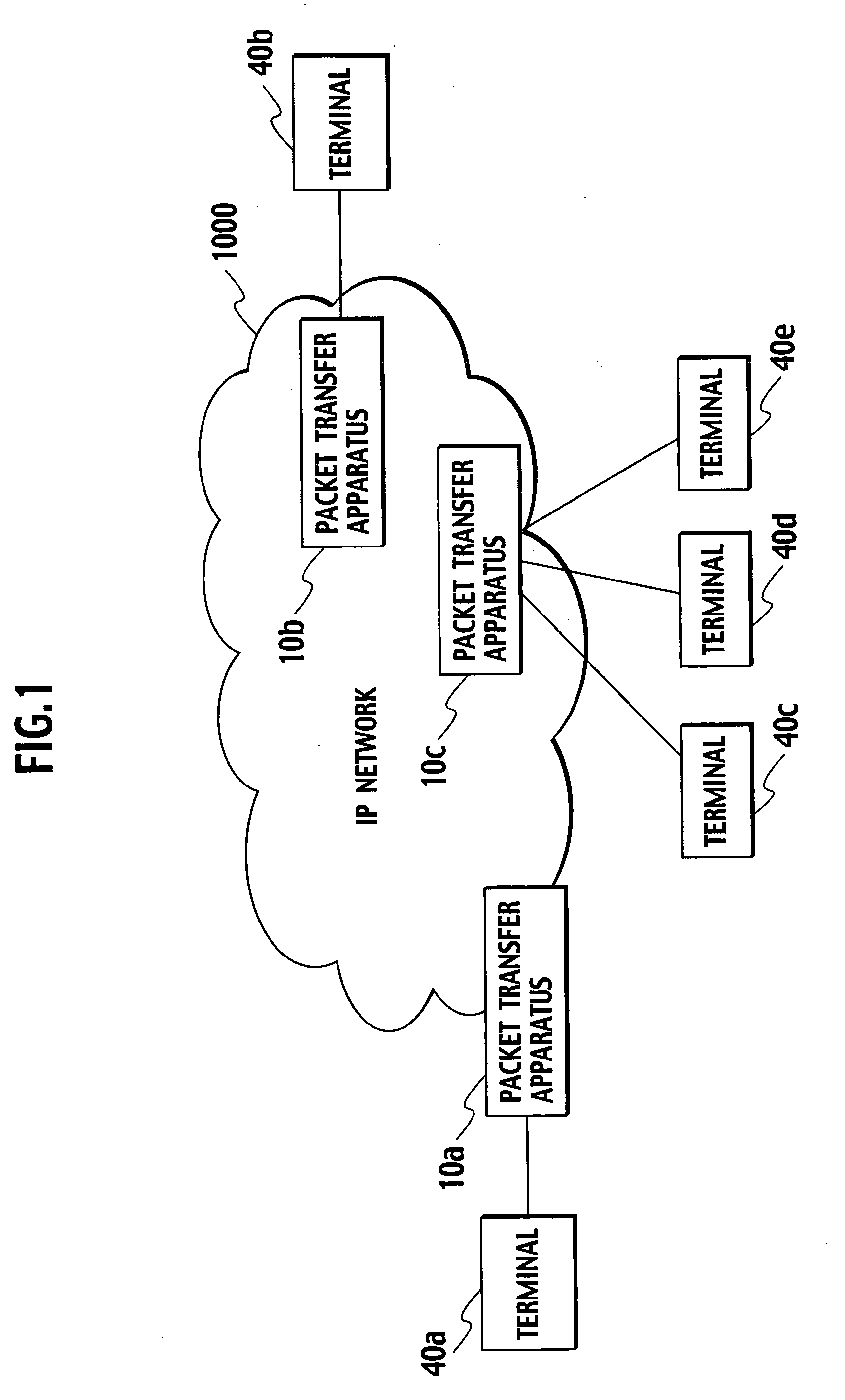
[0193]FIG. 1 is a view showing a general configuration of a retry communication control system according to the present invention.

[0194] In FIG. 1, packet transfer apparatuses 10a to 10c connect terminal apparatuses 40a to 40e to an IP (Internet protocol) network 1000 and transfer IP packets transmitted from the terminal apparatuses 40a to 40e to the IP network 1000. For example, the packet transfer apparatus 10a connects the terminal apparatus 40a to the IP network 1000 and transfers packets of priority and trial classes according to the priorities. The terminal apparatus 40a specifies the priority of a packet to be transferred, i.e., whether the packet must be transferred in the priority class or in the trial class.

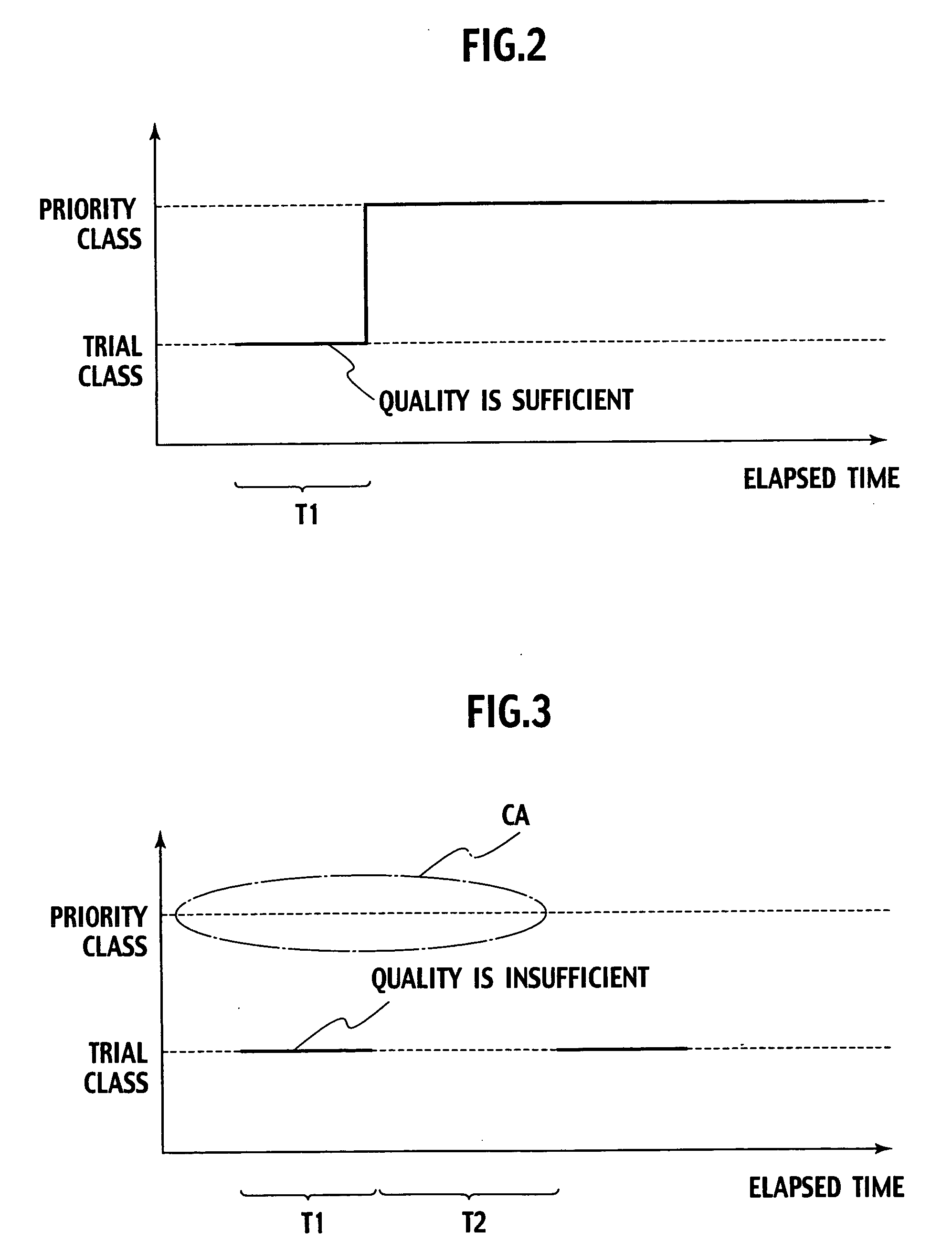
[0195] A first embodiment of a retry communication control method and system according to the present invention will be explained. FIGS. 2 and 3 are views explaining transitions of priorities set for packets according to the first embodiment of the retry communication ...

second embodiment

[0361]FIG. 30 is a view showing a general configuration of the packet transfer system according to the present invention.

[0362] The packet transfer system 1c of this embodiment is characterized in that the address of a packet exchanged in a call to be monitored is rewritten by a packet transfer apparatus accommodating a terminal apparatus that transmits the packet as well as by a monitor apparatus so that the packet is monitored without notifying the terminal apparatus of the address of the monitor apparatus.

[0363] In FIG. 30, the packet transfer system 1c of this embodiment includes a plurality of packet transfer apparatuses 14a to 14d to transfer packets, a call control apparatus 22 to control a call for voice communication and the like between terminal apparatuses 80a and 80b connected to the packet transfer apparatuses 14a and 14d, respectively, and a monitor apparatus 31 to monitor received packets and transfer the same to a specified destination.

[0364] The packet transfer ap...

third embodiment

[0388]FIG. 33 is a view showing a general configuration of the packet transfer system according to the present invention.

[0389] The packet transfer system of this embodiment employs MPLS (multi-protocol label switching) to transfer packets. Between terminal apparatuses, an LSP (label switch path) passing through a monitor apparatus is preset, and if a monitor instruction is issued, the MPLS label of each packet to be monitored is provided with an LSP label to pass through the monitor apparatus, so that the packet may pass through the monitor apparatus.

[0390] In FIG. 33, the packet transfer system id according to the embodiment includes a plurality of packet transfer apparatuses 16a to 16d to transfer packets, a call control apparatus 23 to control a call for voice communication and the like between terminal apparatuses 80a and 80b connected to the packet transfer apparatuses 16a and 16d, respectively, and a monitor apparatus 32 to monitor received packets and transfer the same to a...


PUM


Abstract

A terminal apparatus firstly transfers packets of a trial class. When the communication quality is insufficient, the terminal apparatus determines after a predetermined period of time whether or not to transfer the trail-class packets again according to a traffic rate of priority-class packets. There are provided a trial-class band capacity not to discard packets of the trial class and a priority-class band capacity not to discard packets of the priority class. Trial-class packets exceeding the former are discarded but the packets that has once become a priority class will not be discarded unless the latter is exceeded.

Description

TECHNICAL FIELD [0001] The present invention relates to a retry communication control method and system, a packet transfer possibility determination method, a packet transfer apparatus, a packet transfer system, a packet monitor method, a call control apparatus, a monitor apparatus, and programs. In particular, it relates to a retry communication control method and system, a packet transfer possibility determination method, a packet transfer apparatus, a packet transfer system, a packet monitor method, a call control apparatus, a monitor apparatus, and programs, all of them being based on a measurement-based call admission control system in which a terminal unit sends in a preparatory communication stage test packets in a trial class whose priority is lower than an originally intended priority, and according to a result of the trial communication, sends packets in a priority class of the originally intended priority or again in the trial class, thereby the terminal unit initiatively...

Claims


Application Information

Patent Timeline
IPC IPC(8): G06F15/173H04L47/20H04L47/21H04L47/32
CPCH04L47/10H04L47/11H04L47/20H04L47/215H04L47/2408H04L47/2441H04L47/28H04L47/32
Inventor KOYANAGI, ETSUKOMIYAYAMA, SATOSHIMORITA, NAOTAKAMORI, SHUNSUKE
Owner NIPPON TELEGRAPH & TELEPHONE CORP
Why Eureka
Try Eureka