Thermal and power management apparatus

a technology of power management and power management, applied in the direction of electrical apparatus casings/cabinets/drawers, ventilation systems, domestic cooling apparatuses, etc., can solve the problem of difficult access to readings

Inactive Publication Date: 2006-08-03
HEWLETT-PACKARD ENTERPRISE DEV LP
View PDF36 Cites 291 Cited by
  • Summary
  • Abstract
  • Description
  • Claims
  • Application Information

AI Technical Summary

Problems solved by technology

Data center managers and customers face a growing challenge managing the cooling and electrical specifications of information technology (IT) equipment deployed in data centers.
Typically, manufacturers do not supply system-level airflow specifications and, if specified, only a single maximum airflow requirement is defined in technical documentation that is not readily available to most customers.
Ambient air temperature sensors are integrated into most enterprise-class servers, but readings are difficult to access.

Method used


Image

  • Thermal and power management apparatus
  • Thermal and power management apparatus
  • Thermal and power management apparatus

Examples


Embodiment Construction

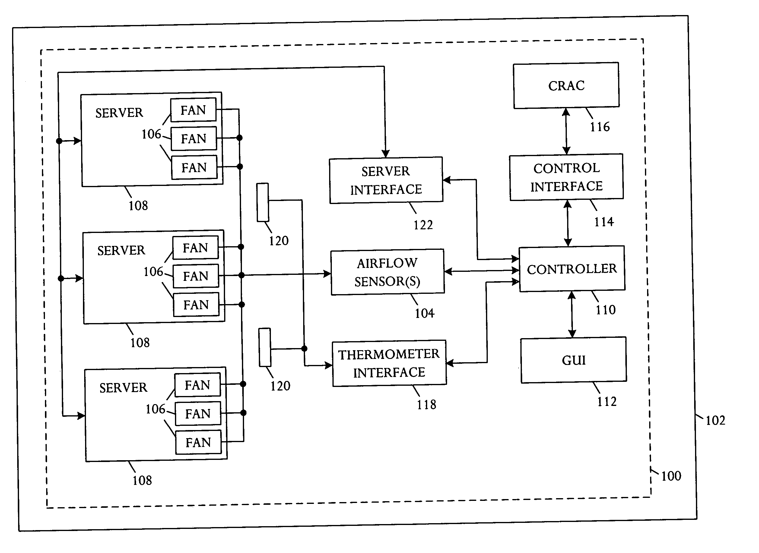
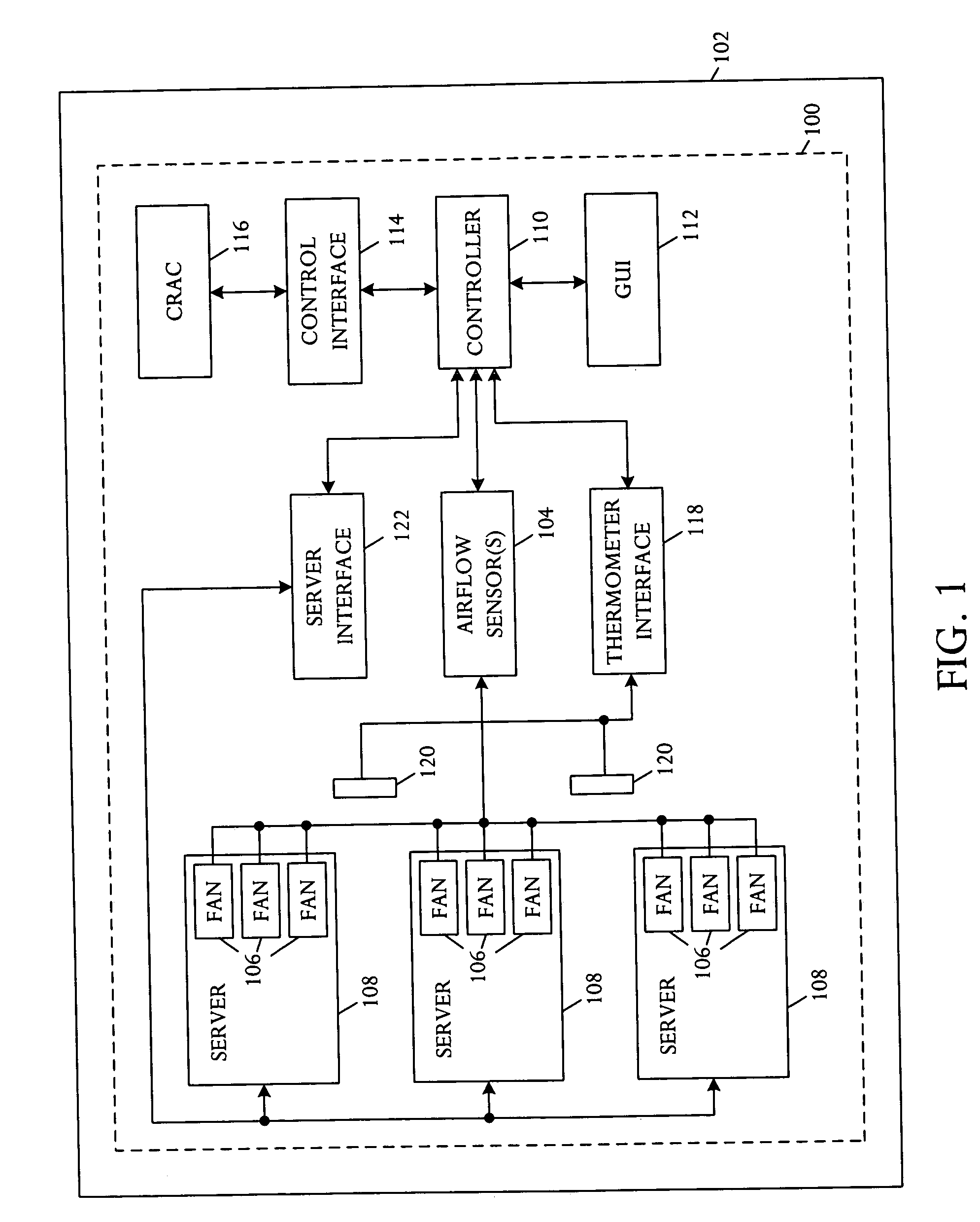
[0011] Referring to FIG. 1, a schematic block diagram illustrates an embodiment of an airflow distribution apparatus 100 for usage in a data center 102. The airflow distribution apparatus 100 comprises one or more airflow sensors 104 coupled to a plurality of fans 106 in one or more servers 108 in the data center 102. A controller 110 is coupled to the airflow sensors 104 and is configured or encoded with a computable readable program code for processing airflow distribution in the data center 102. The controller 110 can monitor airflow for the multiple fans and control cooling in the data center 106 as a function of the sensed airflow.

[0012] In one illustrative embodiment, the airflow sensors 104 can be tachometers, pressure sensors, anemometers, and other types of sensors that can be used to determine airflow measurements. For example, a tachometer may be used to monitor fan speed, typically in revolutions per minute (RPM). Fan speed readings from the tachometer may be converted ...


PUM


Abstract

A method for processing airflow distribution in a data center comprises monitoring airflow in a ventilation system including a plurality of fans in at least one server in the data center, and controlling cooling in the ventilation system as a function of the sensed airflow.

Description

BACKGROUND OF THE INVENTION [0001] Computer system reliability depends on environmental stability. An information technology (IT) facility such as a data center typically includes an environmental control system intended to operate each system within a suitable range of conditions. [0002] Data center managers and customers face a growing challenge managing the cooling and electrical specifications of information technology (IT) equipment deployed in data centers. Power and system-level airflow specifications have increased dramatically over the past decade. Nameplate power information on servers is defined as a maximum value defined for regulatory compliance and, accordingly, is much higher than actual power consumption. Typically, manufacturers do not supply system-level airflow specifications and, if specified, only a single maximum airflow requirement is defined in technical documentation that is not readily available to most customers. Ambient air temperature sensors are integra...

Claims


Application Information

Patent Timeline
Patent Type & Authority Applications(United States)
IPC IPC(8): F24F7/00F25D17/00H05K5/00F25D23/12
CPCF24F11/001F24F11/0012F24F2011/0038H05K7/20836F24F11/30F24F2110/00F24F2110/10F24F2110/30F24F7/007F24F11/0001G06F1/206H05K7/20136
Inventor MALONE, CHRISTOPHER G.LARSON, THANE M.SIMON, GLENN C.
Owner HEWLETT-PACKARD ENTERPRISE DEV LP
Why Eureka
Try Eureka