Fuel density measurement device, system, and method

a fuel density and measurement device technology, applied in the direction of instruments, specific gravity measurement, machines/engines, etc., can solve the problems of fuel environment fraud, device range over which fuel density can be measured, and practice abounds and has not been detected, so as to achieve the effect of convenient computation

Inactive Publication Date: 2006-08-03
VEEDER ROOT
View PDF16 Cites 44 Cited by
  • Summary
  • Abstract
  • Description
  • Claims
  • Application Information

AI Technical Summary

Benefits of technology

[0013] In a second specific embodiment, the bladder of the fuel weight sensor may be shaped like a bellows. This bellows shaped bladder may be positioned on top of the water float. As the weight of the column of fuel changes, the compression of the bellows changes, effectively moving the fuel weight m

Problems solved by technology

To the extent that the adulterated fuel is not what the customer thinks he is purchasing, the fueling environment has committed fraud.
While these fraudulent activities have not been widely detected in the United States, it is possible that the practice abounds a

Method used


Image

  • Fuel density measurement device, system, and method
  • Fuel density measurement device, system, and method
  • Fuel density measurement device, system, and method

Examples


Embodiment Construction

[0024] The embodiments set forth below represent the necessary information to enable those skilled in the art to practice the invention and illustrate the best mode of practicing the invention. Upon reading the following description in light of the accompanying drawing figures, those skilled in the art will understand the concepts of the invention and will recognize applications of these concepts not particularly addressed herein. It should be understood that these concepts and applications fall within the scope of the disclosure and the accompanying claims.

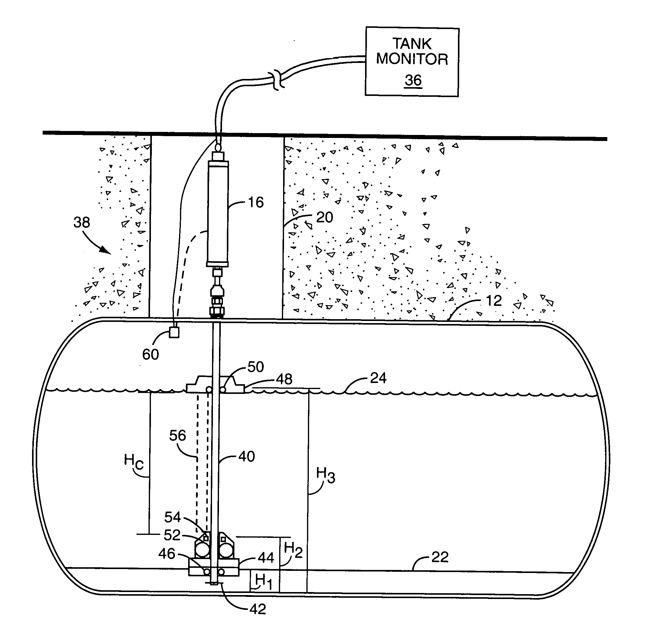
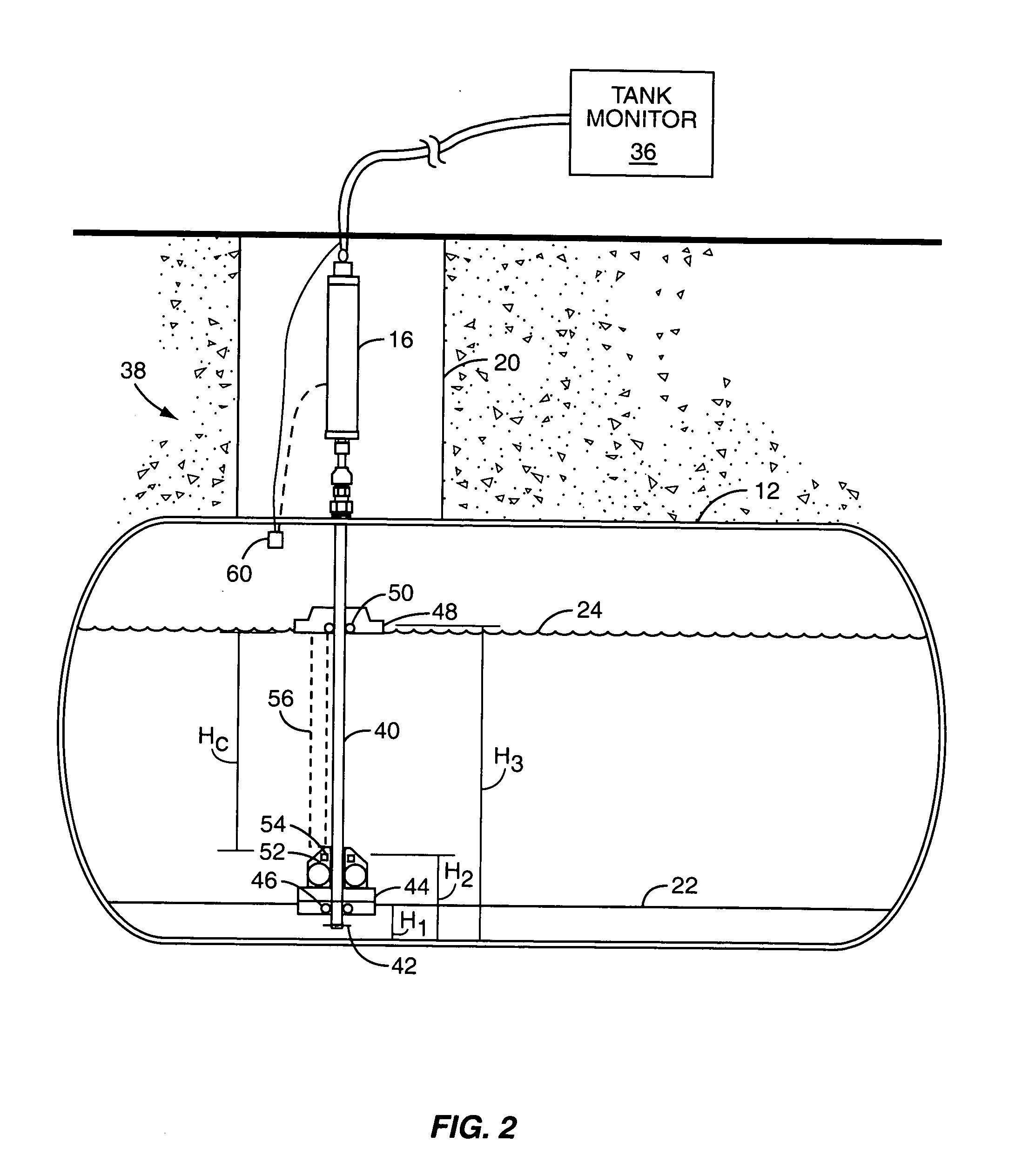
[0025] The present invention is an improvement on a conventional fuel level probe adapted for use in a fuel storage tank. Specifically, the present invention adds a fuel weight sensor to the probe shaft of a magnetostrictive probe operating with a typical fuel float. The fuel weight sensor is, in practice, proximate the bottom of the probe shaft. The fuel weight sensor works to measure the weight of a column of fuel positioned a...


PUM


Abstract

A fuel tank probe includes a water level float and a fuel level float. A fuel weight sensor is incorporated into the fuel tank probe to report the density of the fuel within the tank. The fuel weight sensor includes a compressible bladder whose shape changes as a function of the density of the fuel. A magnet on the compressible bladder moves in conjunction with the changing shape of the compressible bladder, and allows a fuel column height to be measured. The density of the fuel can be determined from the measured fuel column height.

Description

FIELD OF THE INVENTION [0001] The present invention relates to a probe used in a fuel storage tank that detects not only the height of the fuel within the storage tank, but also the density of the fuel within the storage tank. BACKGROUND OF THE INVENTION [0002] Fueling environments typically store fuel in large underground storage tanks. To comply with environmental laws, rules, and regulations, these storage tanks may be double walled and equipped with various leak detection sensors and inventory reconciliation systems. One popular sensor is sold by Veeder-Root Company of 125 Powder Forest Drive, Simsbury, Conn. 06070 under the name “The MAG Plus Inventory Measurement Probe” (Mag Probe) and, this sensor is typically matched with a tank monitor, such as the TLS-350R also sold by Veeder-Root Company. Such probes measure a height of fuel within the storage tank and may optionally measure a height of water (if present). The measurements are then reported to the tank monitor for usage b...

Claims


Application Information

Patent Timeline
IPC IPC(8): G01F23/00
CPCG01F23/2963G01F23/72G01N9/04G01N33/22
Inventor ZALENSKI, THOMASTANCK, CALVIN E.BAGLIONI, ADRIANO
Owner VEEDER ROOT
Why Eureka
Try Eureka