Eureka AIR delivers breakthrough ideas for toughest innovation challenges, trusted by R&D personnel around the world.

Vapor deposition source and vapor deposition apparatus having the same

Active Publication Date: 2006-08-03
SAMSUNG DISPLAY CO LTD
View PDF18 Cites 63 Cited by
  • Summary
  • Abstract
  • Description
  • Claims
  • Application Information

AI Technical Summary

Problems solved by technology

Because adiabatic materials should be installed at a large vapor deposition source, installation cost of the adiabatic materials is also increased.
Moreover, a conveyer for conveying the vapor deposition source requires high power.

Method used


Image

  • Vapor deposition source and vapor deposition apparatus having the same
  • Vapor deposition source and vapor deposition apparatus having the same
  • Vapor deposition source and vapor deposition apparatus having the same

Examples


Embodiment Construction

[0031] Hereinafter, preferable embodiments of a vapor deposition source and a vapor deposition apparatus having the vapor deposition source according to the present invention will be described with reference to the accompanying drawings. In this regard, when one element is connected to another element, the one element may be not only directly connected to the other element but also indirectly connected to the other element via a third element. Furthermore, unrelated ro irrelevant elements are omitted for clarity. Also, like reference numerals refer to like elements throughout.

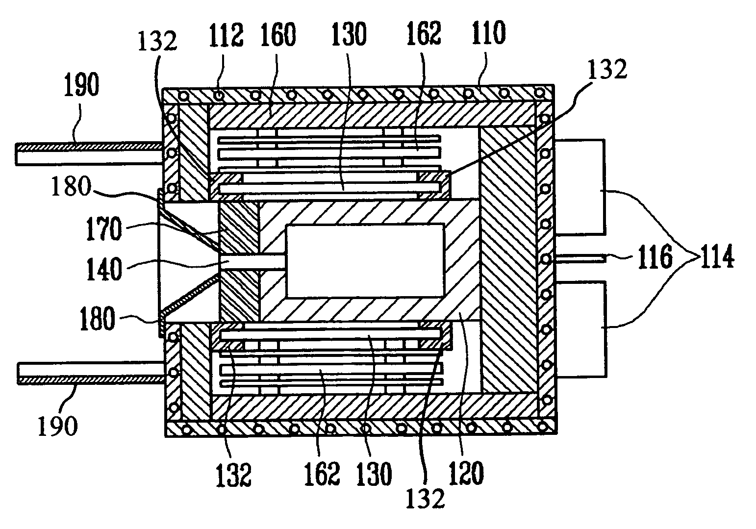
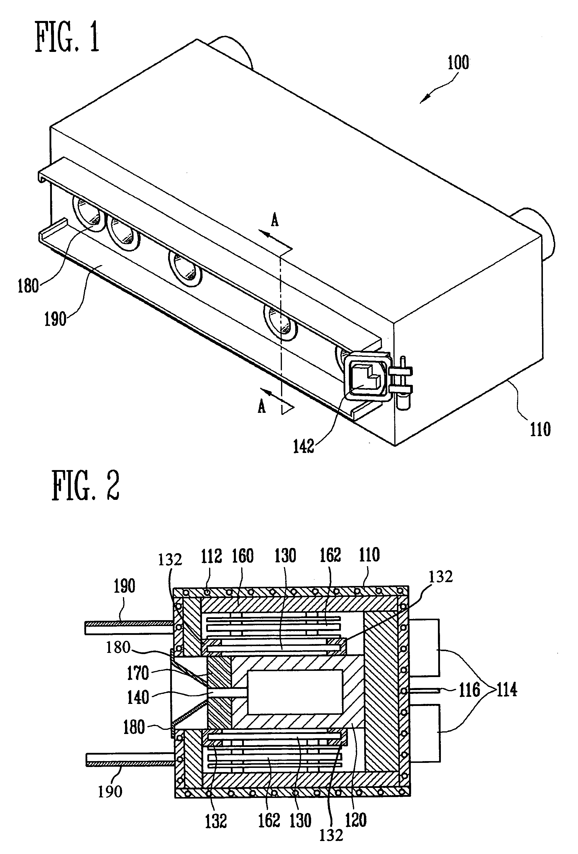
[0032]FIG. 1 is a perspective view of a vapor deposition source according to a preferred embodiment of the present invention, and FIG. 2 is a cross-sectional view of the vapor deposition source taken along line A-A′ of FIG. 1.

[0033] With reference to FIG. 1 and FIG. 2, the vapor deposition source 100 of the present invention includes a housing 110, a crucible 120, a heater 130, adiabatic material 160, and an ...


PUM

PropertyMeasurementUnit
Lengthaaaaaaaaaa
Diameteraaaaaaaaaa
Diameteraaaaaaaaaa

Abstract

A vapor deposition source has a reduced size by disposing a crucible, a heating portion, and a nozzle portion in one defined space. A vapor deposition apparatus deposits deposition materials on a substrate using the vapor deposition source. The vapor deposition source includes a housing, and the crucible is mounted in the housing for vaporizing the deposition materials. The heating portion is installed adjacent to the crucible in the housing for heating the crucible. The nozzle portion injects the vaporized deposition materials into a substrate disposed at an exterior of the housing through an injection nozzle. The vapor deposition source is manufactured in a smaller and lightweight form in comparison with conventional vapor deposition sources in which a crucible and a nozzle portion are arranged in different spaces. The diameter and number of injection nozzles of the invention are restricted to block radiant heat discharged from the vapor deposition source, so that deposition materials are uniformly deposited. Furthermore, the output power of a conveyer for conveying the vapor deposition source is reduced. In addition, a plurality of vapor deposition sources is arranged in a line to perform concentrated deposition of deposition materials so that quality of the resultant product is improved.

Description

CLAIM OF PRIORITY [0001] This application makes reference to, incorporates the same herein, and claims all benefits accruing under 35 U.S.C. §119 from applications for VAPOR DEPOSITION SOURCE AND VAPOR DEPOSITION APPARATUS HAVING THE SAME earlier filed in the Korean Intellectual Property Office on 31 Jan. 2005 and 15 Apr. 2005, and there duly assigned Serial Nos. 2005-8793 and 2005-31684, respectively. BACKGROUND OF THE INVENTION [0002] 1. Technical Field [0003] The present invention relates to a vapor deposition source and a vapor deposition apparatus having the same, and more particularly to a vapor deposition source including a housing, a crucible and a nozzle portion mounted in the housing, and a vapor deposition apparatus having the same. [0004] 2. Related Art [0005] Generally, vapor deposition apparatuses are used to deposit a thin film on various kinds of electronic components, and more particularly to form a thin film on semiconductor devices and display devices, such as liq...

Claims


Application Information

Patent Timeline
IPC IPC(8): C23C16/00
CPCC23C14/24C23C14/243
Inventor KIM, DO GEUNHUH, MYUNG SOOJEONG, SEOK HEONKANG, HEE CHEOLFURUNO, KAZUO
Owner SAMSUNG DISPLAY CO LTD
Why Eureka
Eureka Blog
Learn More