
Vehicle with clutch assist device

a technology of assist device and clutch, which is applied in the direction of clutch, mechanical control device, controlling member, etc., to achieve the effect of not reducing the assist force of the auxiliary force member, small size, and easy mounting of the clutch assist devi

Inactive Publication Date: 2006-08-03
YAMAHA MOTOR CO LTD
View PDF19 Cites 48 Cited by
  • Summary
  • Abstract
  • Description
  • Claims
  • Application Information

AI Technical Summary

Benefits of technology

The present invention is about a clutch assist device that helps to engage or disengage a clutch. The device includes a rotatable member and an auxiliary force member that applies an assist force to help disengage the clutch. The device is small in size and can be easily mounted on a vehicle. It also allows for a smooth movement of the clutch wire and improves the operability of the clutch operator. The technical effects of this invention are improved operability and compact design.

Problems solved by technology

Therefore, in the case where the clutch wire or the like has to be curved sharply at a mid-portion because of limitations in installing the clutch wire or like design limitations, the use of the rotatable member permits the first and second sections of the wire to lie skewed relative to each other.

Method used


Image

  • Vehicle with clutch assist device
  • Vehicle with clutch assist device
  • Vehicle with clutch assist device

Examples


first embodiment

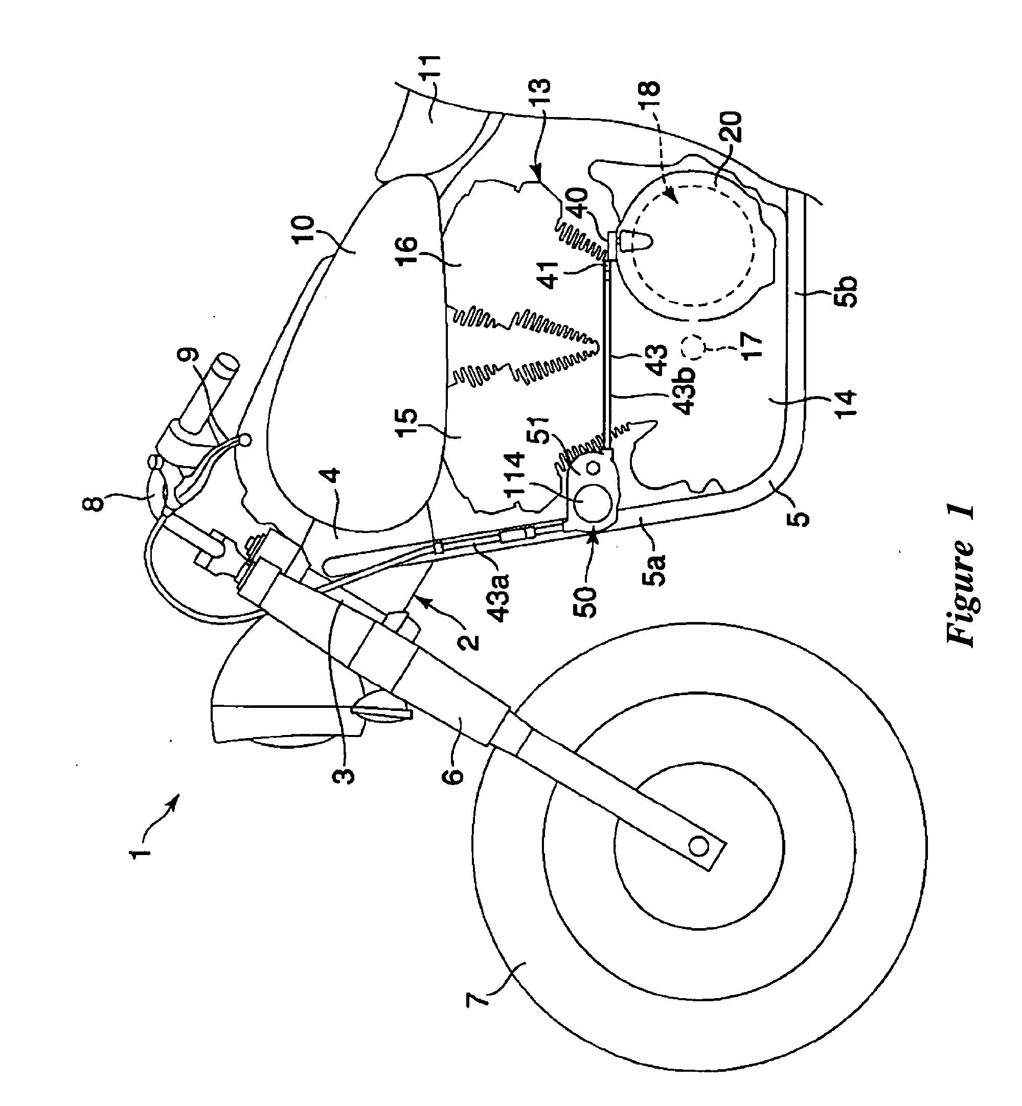
[0057] With initial reference to FIGS. 1 and 2, a motorcycle, which includes the present clutch assist device, has a frame 2. The frame 2 includes a steering head pipe 3, a main frame member 4 and a down tube 5. The steering head pipe 3 supports a front fork 6. To the upper end of the front fork 6 is secured a handlebar 8 for steering a front wheel 7. A clutch lever 9 is attached to the left end of the handlebar 8. The clutch lever 9 is one example of the type of clutch operator with which the present clutch assist device can be used. While the clutch operator is manually operated by hand in this embodiment, the clutch operator can be operated by foot or otherwise by the vehicle's rider.

[0058] The main frame member 4 extends backward from the steering head pipe 3. The main frame member 4 supports a fuel tank 10 and a seat 11. The down tube 5 has a first portion 5a extending downward from the front end of the main frame member 4 and a second portion 5b extending backward from the lo...

second embodiment

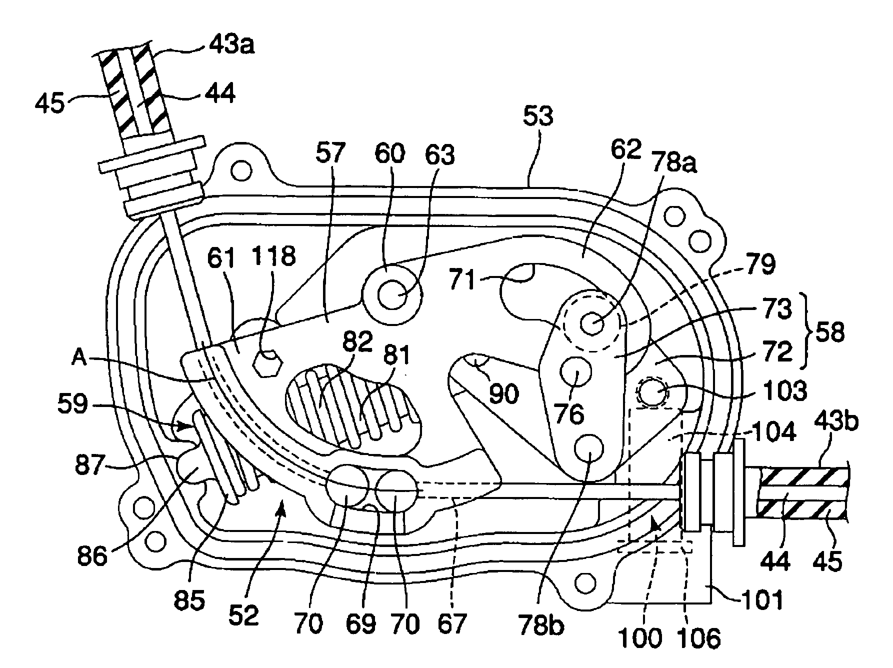
[0131] In the second embodiment, the clutch assist device 50 according to the first embodiment is modified as shown in FIG. 16 to FIG. 25. The clutch assist device 50 of the first embodiment is further decreased in size in accordance with the second embodiment of a clutch assist device. In the following description, those parts corresponding to the components of the first embodiments are identified with the same reference numerals.

[0132] As shown in FIG. 16 to FIG. 18, the second embodiment of the clutch assist device 50 also preferably has an exterior case 51 and an assist mechanism 52. The exterior case 51 has a case body 53 and a case cover 54. In the second embodiment, the areas of the case body 53 and the case cover 54 as viewed from a side are smaller than those in the first embodiment.

[0133] As shown in FIG. 16 and FIG. 18, each of the case body 53 and the case cover 54 has first, second and third fastening parts 151, 152 and 153, each having a bolt hole. The case body 53 a...


PUM


Abstract

A compact clutch assist device has an assist mechanism operating between a clutch operating lever and a transmission clutch. The clutch assist device is interposed between a first clutch wire connected to the clutch operating lever and a second clutch wire connected to the transmission clutch. The clutch assist device selectively urges the clutch wires in such a direction as to assist disengaging the transmission clutch. The clutch assist mechanism has a case and a rotatable member that is housed in the case. The rotatable member receives an urging force of an auxiliary force member. In one embodiment, the auxiliary force member is coupled to the rotatable member through a cam mechanism.

Description

CROSS-REFERENCE TO RELATED APPLICATIONS [0001] This application is based on and claims priority under 35 U.S.C. § 119(a)-(d) to Japanese Patent Application No. 2005-128070, filed Apr. 26, 2005, and to Japanese Patent Application No. 2005-002873, filed Jan. 7, 2005, the entire contents of which are hereby incorporated by reference. BACKGROUND OF THE INVENTION [0002] 1. Field of the Invention [0003] The present invention relates to a clutch assist device which can reduce the force necessary to operate a friction clutch to engage and disengage a transmission of a vehicle. [0004] 2. Description of the Related Art [0005] An engine unit of a vehicle, for example a motorcycle, is often equipped with a friction clutch that operates to engage and disengage a transmission. With the clutch engages, the transmission transfers torque from the engine crankshaft to one or more wheels of the motorcycle and, with the clutch disengaged, the transmission is decoupled from the engine so as not transfer...

Claims


Application Information

Patent Timeline
Patent Type & Authority Applications(United States)
IPC IPC(8): B62K23/02
CPCF16D23/12G05G1/085
Inventor OOISHI, AKIFUMIISHIDA, YOUSUKE
Owner YAMAHA MOTOR CO LTD
Features
  • Generate Ideas
  • Intellectual Property
  • Life Sciences
  • Materials
  • Tech Scout
  • Unparalleled Data Quality
  • Higher Quality Content
  • 60% Fewer Hallucinations
Learn More