Wire ultrasonic bonding method and wire ultrasonic bonding apparatus

a wire ultrasonic and ultrasonic technology, applied in the direction of soldering apparatus, manufacturing tools,auxillary welding devices, etc., can solve the problems of b>101/b>core wires being liable to be cut, and achieve good bonding performance and high adhesion.

Inactive Publication Date: 2006-08-03
YAZAKI CORP
View PDF16 Cites 22 Cited by
  • Summary
  • Abstract
  • Description
  • Claims
  • Application Information

AI Technical Summary

Benefits of technology

[0018] In the above wire ultrasonic bonding apparatus, the portion of the die for contact with the connecting portion conforms in shape to the connecting portion, and therefore there can be obtained the wire ultrasonic bonding apparatus in which the high adhesion of the wire conductive portion to the connecting portion can be secured, so that the good bonding

Problems solved by technology

However, large stresses due to the two ultrasonic bonding operations act on the conductive portion

Method used


Image

  • Wire ultrasonic bonding method and wire ultrasonic bonding apparatus
  • Wire ultrasonic bonding method and wire ultrasonic bonding apparatus
  • Wire ultrasonic bonding method and wire ultrasonic bonding apparatus

Examples


Embodiment Construction

[0024] A preferred embodiment of the present invention will now be described.

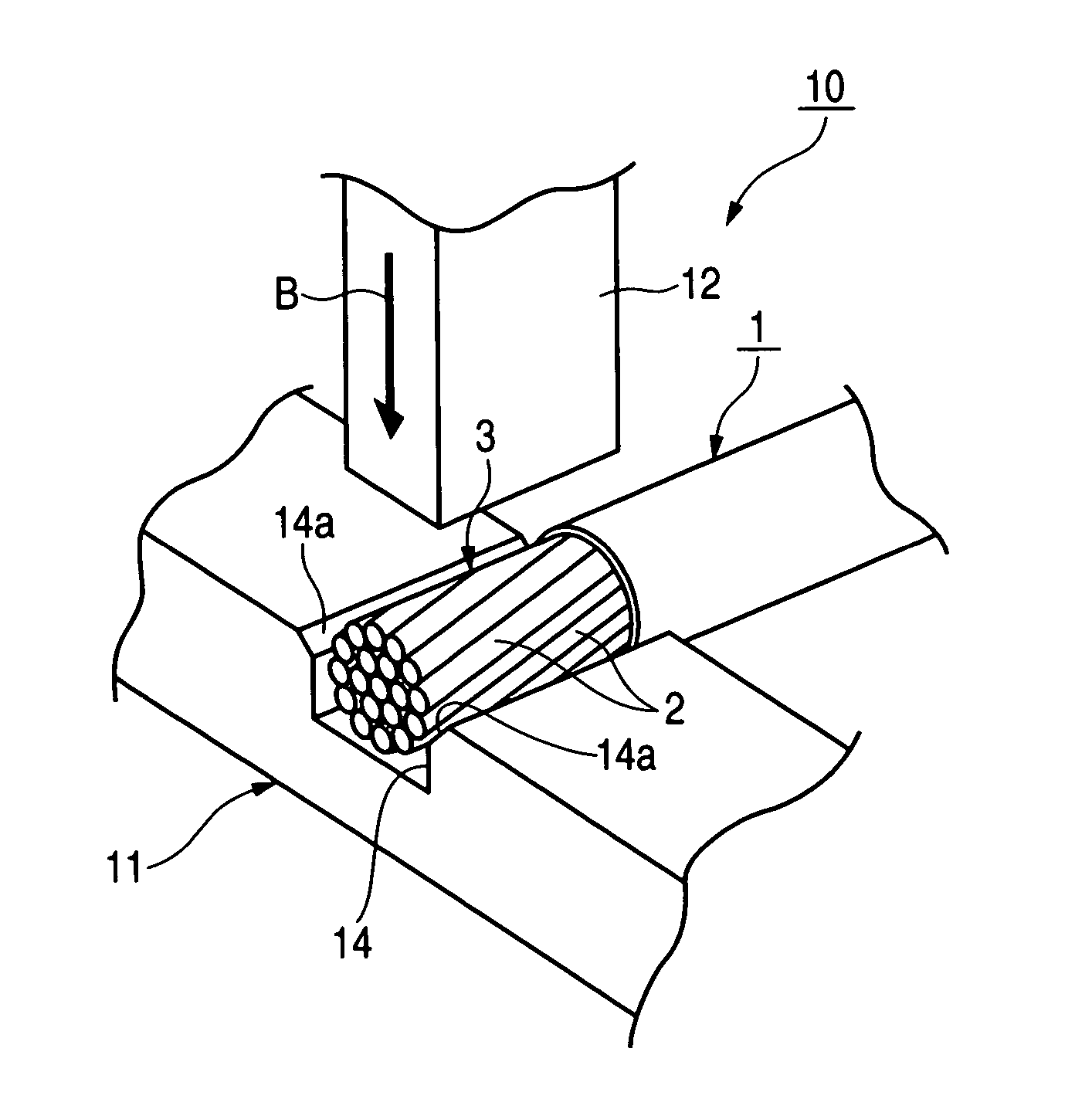
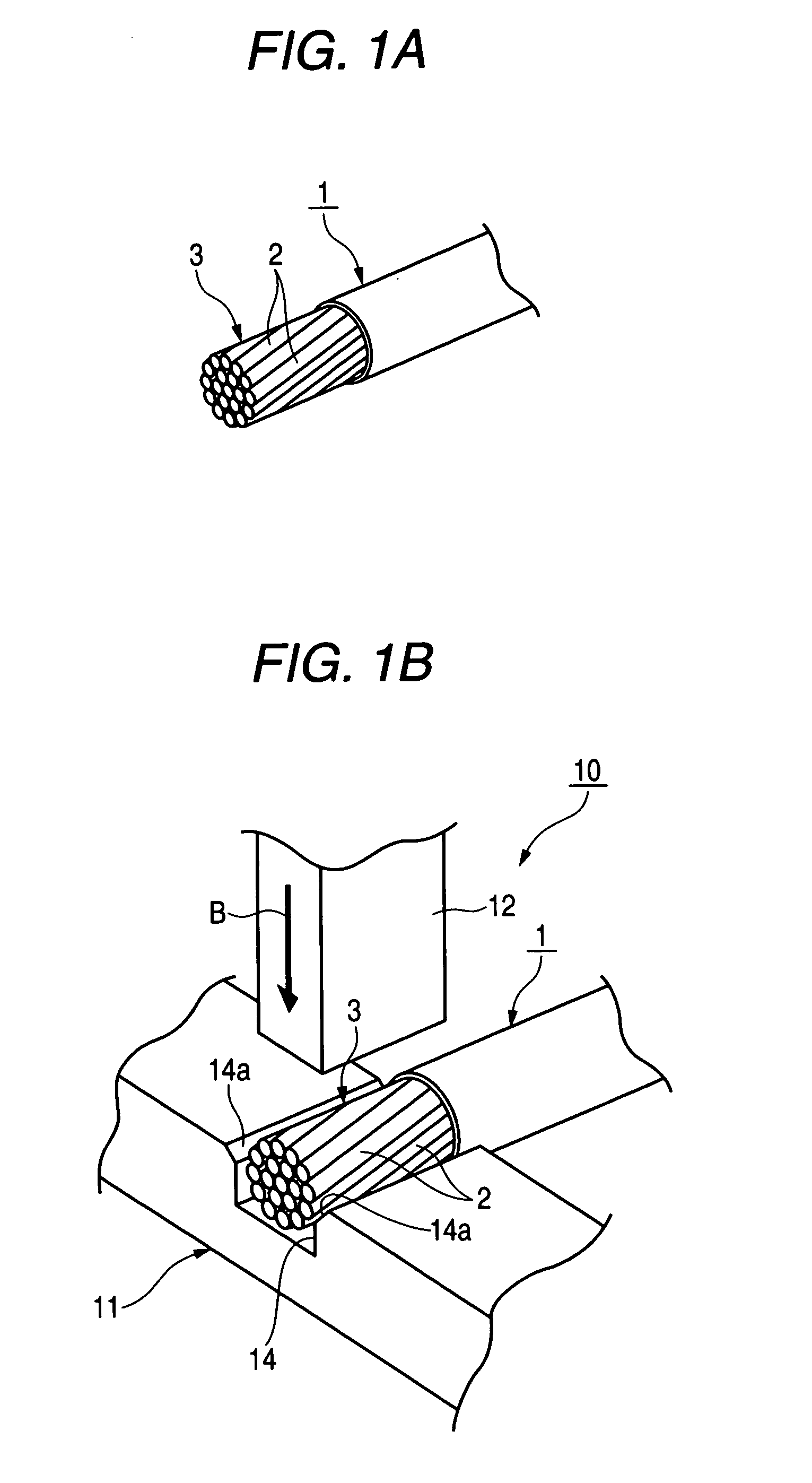
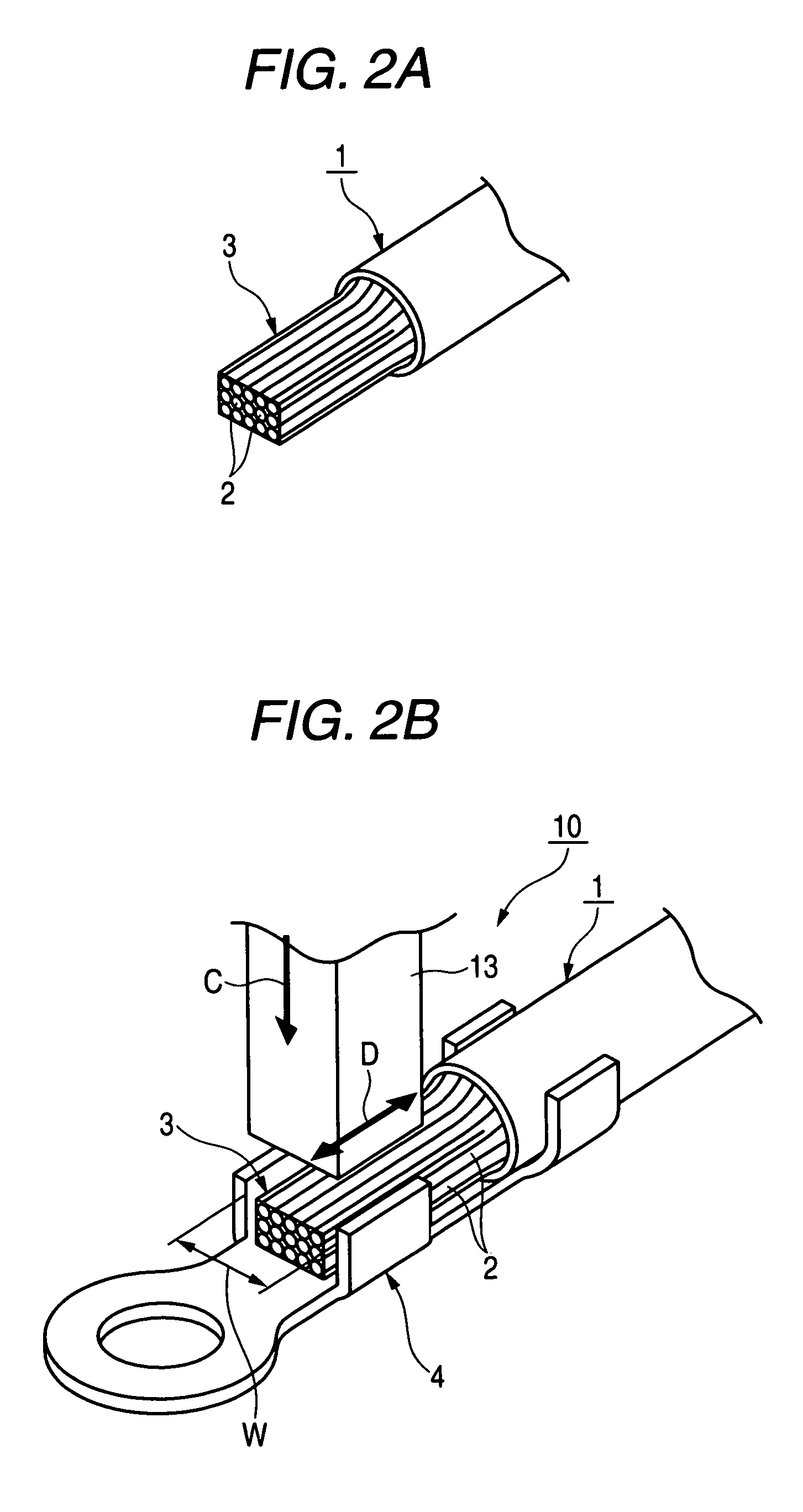
[0025]FIGS. 1A through 2B are perspective views of important portions, showing one preferred embodiment of a wire ultrasonic bonding method of the invention and a wire ultrasonic bonding apparatus of the invention, and FIG. 1A show a wire which is already subjected to a sheath removing operation, but is not yet subjected to a bonding operation, FIG. 1B shows the wire and a press forming machine for pressing a conductive portion of the wire into a flat shape, FIG. 2A shows the wire whose conductive portion is pressed into the flat shape by the press forming machine, and FIG. 2B shows the wire whose conductive portion, while pressed by a horn, is to be ultrasonically bonded to a terminal by the horn.

[0026] First, the wire ultrasonic bonding apparatus 10 for performing one preferred embodiment of the wire ultrasonic bonding method of the invention will be described with reference to FIGS. 1A through 2B.

[002...


PUM

PropertyMeasurementUnit
Thicknessaaaaaaaaaa
Pressureaaaaaaaaaa
Widthaaaaaaaaaa

Abstract

A conductive portion of a wire, composed of a plurality of core wires, is inserted and fitted into a groove in a pressing die, thereby restricting the conductive portion to a bonding width of a terminal, and in this condition with the use of a press forming machine, the conductive portion is pressed in a thickness direction thereof to be formed into a flat shape. Thereafter, the conductive portion is inserted and fitted into the terminal, and then the conductive portion, while pressed by a pressing vibration horn, is bonded to the terminal by ultrasonic vibrations applied from the pressing vibration horn.

Description

BACKGROUND OF THE INVENTION [0001] 1. Field of the Invention [0002] This invention relates to a wire ultrasonic bonding method and a wire ultrasonic bonding apparatus for bonding a wire (such as a stranded wire), having a plurality of core wires, to a connecting portion such as a terminal. [0003] 2. Related Art [0004] A method of ultrasonic bonding a wire is already known (see, for example, Japanese Patent Publication No. JP-A-2004-095293, (Page 3 to 5)). FIGS. 3A through 4B are perspective views showing a wire ultrasonic bonding method disclosed in JP-A-2004-095293. [0005] Referring to FIGS. 3A through 4B, in the wire ultrasonic bonding method, a conductive portion 102 (see FIG. 3A) of a wire 100, composed of a plurality of core wires 101 is restricted to a width corresponding to a bonding width W (see FIG. 4B) of a terminal 103, and in this condition the core wires 101 are ultrasonically bonded together (a first ultrasonic bonding operation) while applying a pressure to the core w...

Claims


Application Information

Patent Timeline
IPC IPC(8): B23K37/00B23K1/06B23K31/00
CPCH01R4/187H01R43/0207H01R11/12
Inventor FUJIMOTO, KEIONUMA, MASANORI
Owner YAZAKI CORP
Why Eureka
Try Eureka