Active polarization-resolving infrared imager

a technology of infrared imager and polarization, applied in the direction of instruments, color/spectral property measurements, optical radiation measurement, etc., can solve the problems of many unknowns, unintended changes in the polarization to be measured, and detriment of target identification accuracy

Inactive Publication Date: 2006-08-03
GROBMYER JOSEPH E +1
View PDF9 Cites 11 Cited by
  • Summary
  • Abstract
  • Description
  • Claims
  • Application Information

AI Technical Summary

Problems solved by technology

However, for the last-mentioned application, infrared polarimetry is still a relatively immature technology that is not currently a part of fielded military hardware.
The reasons are that the instrumentation developed for research and development endeavors is limited in sensitivity and optical components in such instrumentation, as well as optical coatings, scattering and birefringence effects in the instrument, can cause unintended changes in the polarization to be measured, all to the detriment of target identification accuracy.
However, due to the limitations of current infrared polarimetric instrumentation, there are still many unknowns in the process of characterizing military targets in a natural or man-made clutter background.

Method used


Image

  • Active polarization-resolving infrared imager
  • Active polarization-resolving infrared imager
  • Active polarization-resolving infrared imager

Examples


Embodiment Construction

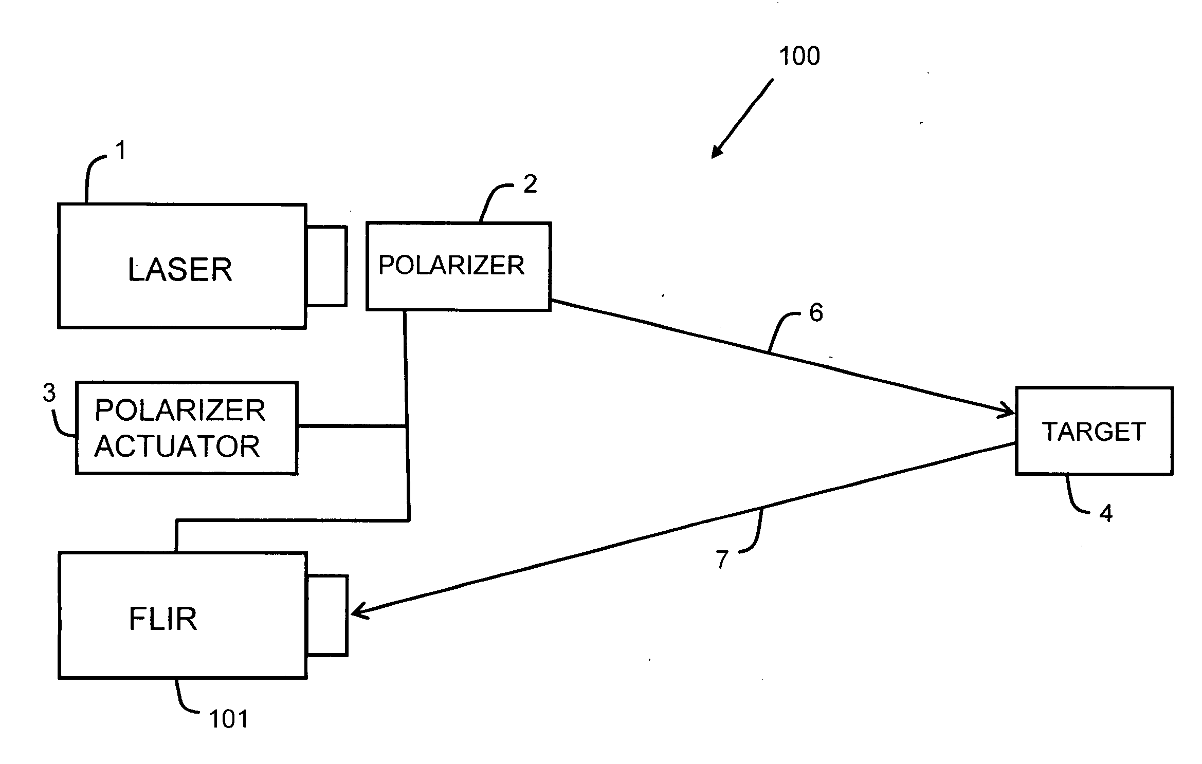
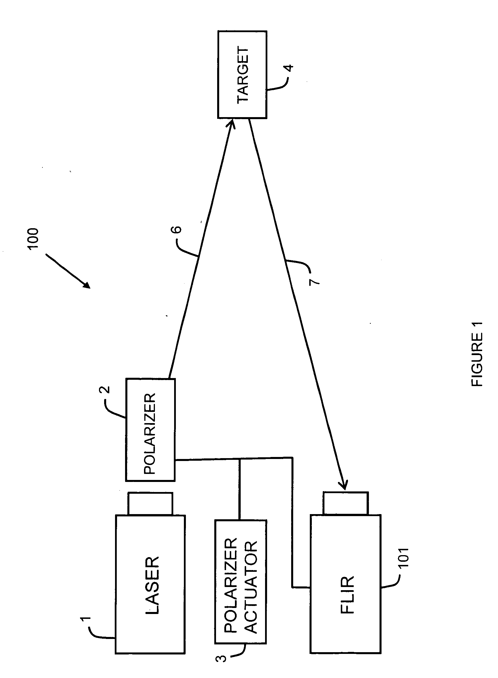
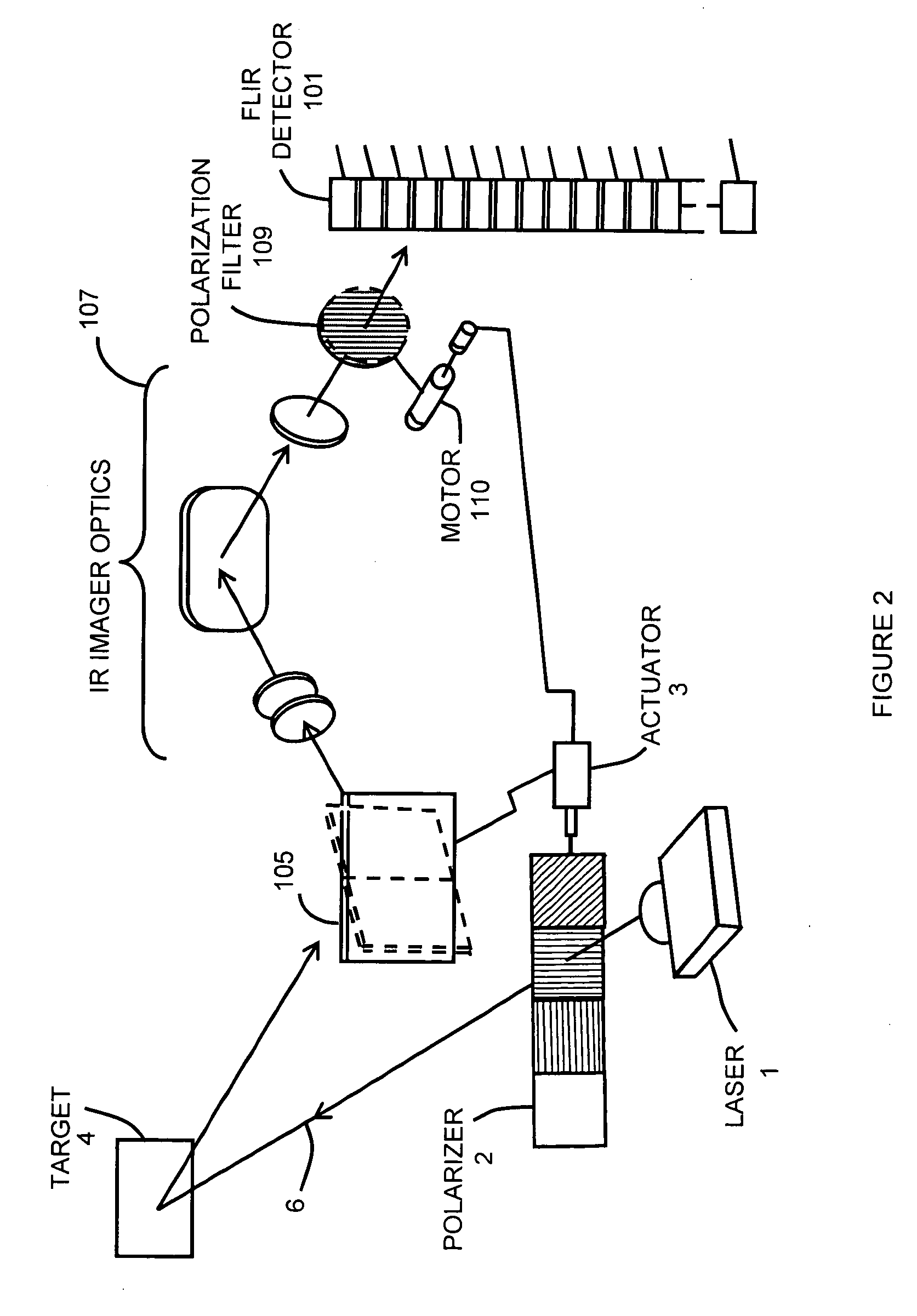
[0009] Referring now to the drawing wherein like numbers represent like parts in each of the several figures and solid lines with arrow heads indicate beam paths (unless otherwise stated in the drawing) while solid lines without arrow heads indicate mechanical or electronic connection, the structure and operation of active polarization-resolving infrared imager 100 (hereinafter referred to as “the active imager”) is explained in detail. As this active imager teaches a significant improvement of the passive means disclosed in U.S. Pat. No. 6,310,345, the teaching of U.S. Pat. No. 6,310,345 is hereby incorporated in its entirety into the instant application.

[0010] The passive mode of measurement utilized in U.S. Pat. No. 6,310,345 relies on the intensity of the received radiation which, in turn, depends on the time of the day, the angle of incidence and whether the article from which the radiation is received is hot or cold. There are many unknowns and uncontrolled factors associated...


PUM


Abstract

The Active Polarization-Resolving Infrared Imager improves the function of the passive polarization-resolving infrared imager of U.S. Pat. No. 6,310,345 by employing a laser to illuminate actively the selected target scene and a means for selectively changing the polarization orientation of the beam emitted by the laser. The polarization of the outgoing beam is maintained in synchronism with the orientation of the polarization filters associated with the passive detector device. As a result, the received signals are maximized on the items or articles in the target scene that preserve the original polarization. Such items (usually man-made) stand out against random nature background which tends to diffuse polarization. Thus, the user of the active imager is more accurately cued to non-naturally occurring areas or objects of interest, such as tanks and other items containing geometric structure, due to relatively high degree of polarization preservation by such items.

Description

DEDICATORY CLAUSE [0001] The invention described herein may be manufactured, used and licensed by or for the Government for governmental purposes without the payment of any royalties to us.BACKGROUND OF THE INVENTION [0002] Infrared polarimetry has potential applications in astronomy, space exploration, material characterization, semiconductor manufacturing, microscopy for biological measurements and, not the least of all, characterization of military targets. However, for the last-mentioned application, infrared polarimetry is still a relatively immature technology that is not currently a part of fielded military hardware. The reasons are that the instrumentation developed for research and development endeavors is limited in sensitivity and optical components in such instrumentation, as well as optical coatings, scattering and birefringence effects in the instrument, can cause unintended changes in the polarization to be measured, all to the detriment of target identification accur...

Claims


Application Information

Patent Timeline
Patent Type & Authority Applications(United States)
IPC IPC(8): G01J5/02
CPCG01N21/21G01N21/35G01N21/3563
Inventor GROBMYER, JOSEPH E.PITTMAN, WILLIAM C.
Owner GROBMYER JOSEPH E
Why Eureka
Try Eureka