Ratcheting winch with a magnetically biased pawl

Inactive Publication Date: 2006-08-03
GILMAN JEFFRY S
View PDF5 Cites 11 Cited by
  • Summary
  • Abstract
  • Description
  • Claims
  • Application Information

AI Technical Summary

Benefits of technology

[0018] It is yet still another object of the present invention to provide a winch as described abov

Problems solved by technology

With the pawl manually disengaged from the ratchet wheel, the tension within the wire will cause the wire to unwind from the drum (i.e., loosen).
Although well known in the art, winches of the type as described above which include a pawl biased by a spring suffer from a couple notable drawbacks.
As a first drawback, winches of the type as described above which utilize a spring for disposing a pawl into selective engagement with a ratchet wheel have been found to be highly unreliable in nature.
In particular,

Method used


Image

  • Ratcheting winch with a magnetically biased pawl
  • Ratcheting winch with a magnetically biased pawl
  • Ratcheting winch with a magnetically biased pawl

Examples


Example

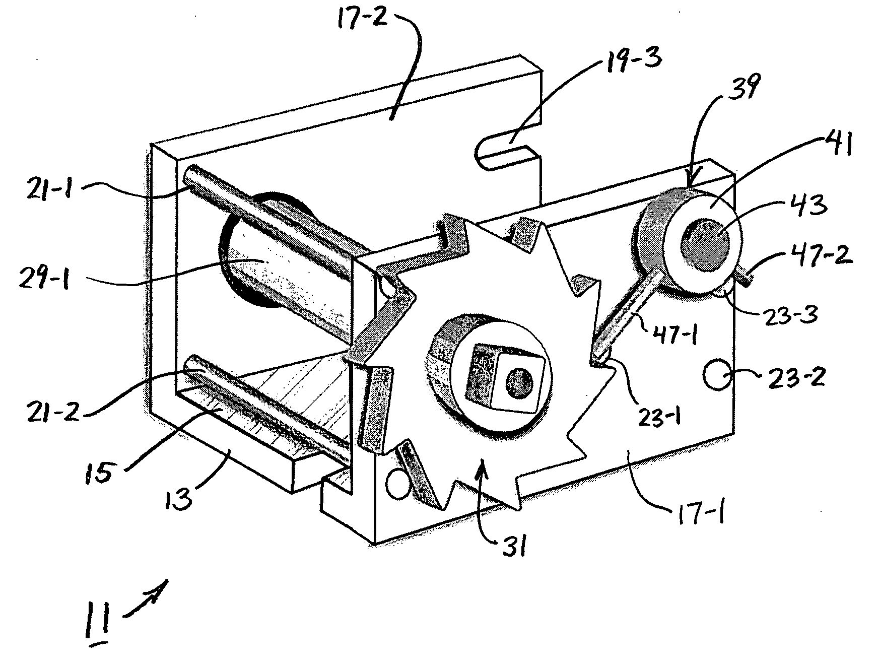
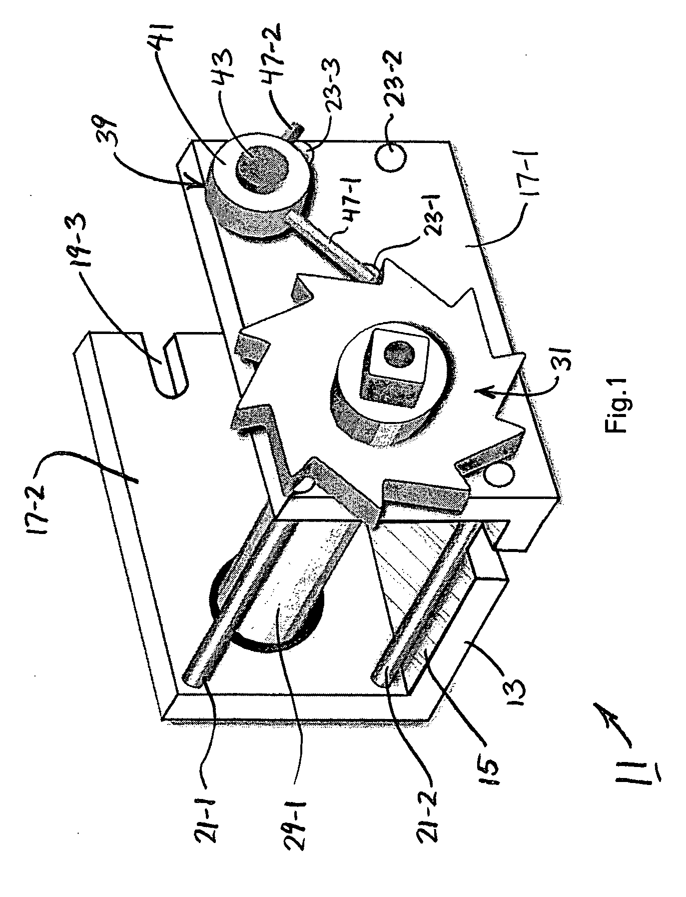
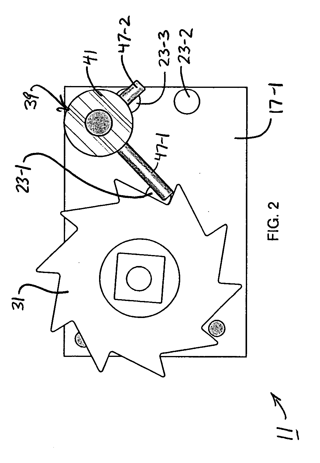
[0031] Referring now to FIGS. 1-5, there are shown perspective, front, rear, top and left end views, respectively, of a novel winch, the winch being constructed according to the teachings of the present invention and identified generally by reference numeral 11. As will be described in detail below, winch 11 can be used to (1) support one end of a length of wire and, with the other end of the wire held fixed in place, (2) provide mechanical means for both tightening and loosening said length of wire.

[0032] Winch 11 includes a unitary U-shaped frame 13 which serves as the structural support on which the remaining components for winch 11 are mounted. Frame 13 is preferably constructed out of a rigid and durable material, such as metal, and includes a flat bottom wall 15 and a pair of spaced apart sidewalls 17-1 and 17-2, each sidewall 17 extending generally orthogonally up from the top surface of flat bottom wall 15.

[0033] It should be noted that bottom wall 15 is shaped to define a...


PUM

PropertyMeasurementUnit
Lengthaaaaaaaaaa
Angleaaaaaaaaaa
Magnetic forceaaaaaaaaaa

Abstract

A winch for controlling the tautness of a length of wire includes a generally U-shaped frame and a spindle rotatably mounted on the frame, the spindle serving as a spool on which the length of wire can be wound. The winch additionally includes a ratchet rotatably mounted on the frame in co-axial alignment with the spindle, the ratchet being fixedly connected to one end of the spindle using the combination of a threaded bolt and a washer. Furthermore, the winch includes a pawl pivotally mounted on the frame, the pawl capable of being pivoted between a first position in which the pawl sequentially engages outwardly extending teeth in the ratchet so as to limit rotation of the ratchet in only one direction and a second position in which the pawl disengages from the ratchet to allow for rotation of the ratchet in either of two opposing directions. First, second and third rare earth magnets are mounted in the frame and, in combination with a pair of outwardly projecting ferritic arms provided in the pawl, serve to magnetically bias the pawl into either of its first and second positions.

Description

CROSS-REFERENCE TO RELATED APPLICATIONS [0001] The present application claims the benefit under 35 U.S.C. 119(e) of U.S. provisional Patent Application Ser. No. 60 / 614,936, filed Sep. 30, 2004, the disclosure of which is incorporated herein by reference.BACKGROUND OF THE INVENTION [0002] The present invention relates generally to winches and more particularly to winches which comprise a rotatable ratchet wheel that can be locked in place using a pivotable pawl. [0003] In the retail industry, it is well known for a length of light to medium gauge wire to be secured at each of its ends to a fixed object, such as a pole, post or wall. With the length of wire held taut between the pair of fixed objects, articles for sale are often hung upon the wire at a considerable height above floor level in order to maximize their visibility. Examples of retail environments in which a length of wire is used to display products for sale include art galleries, trade shows, conventions, and warehouse o...

Claims


Application Information

Patent Timeline
IPC IPC(8): B21F9/00B66F3/00
CPCB66D3/02
Inventor GILMAN, JEFFRY S.
Owner GILMAN JEFFRY S
Why Eureka
Try Eureka