Resonant DC-DC converter of multi-output type

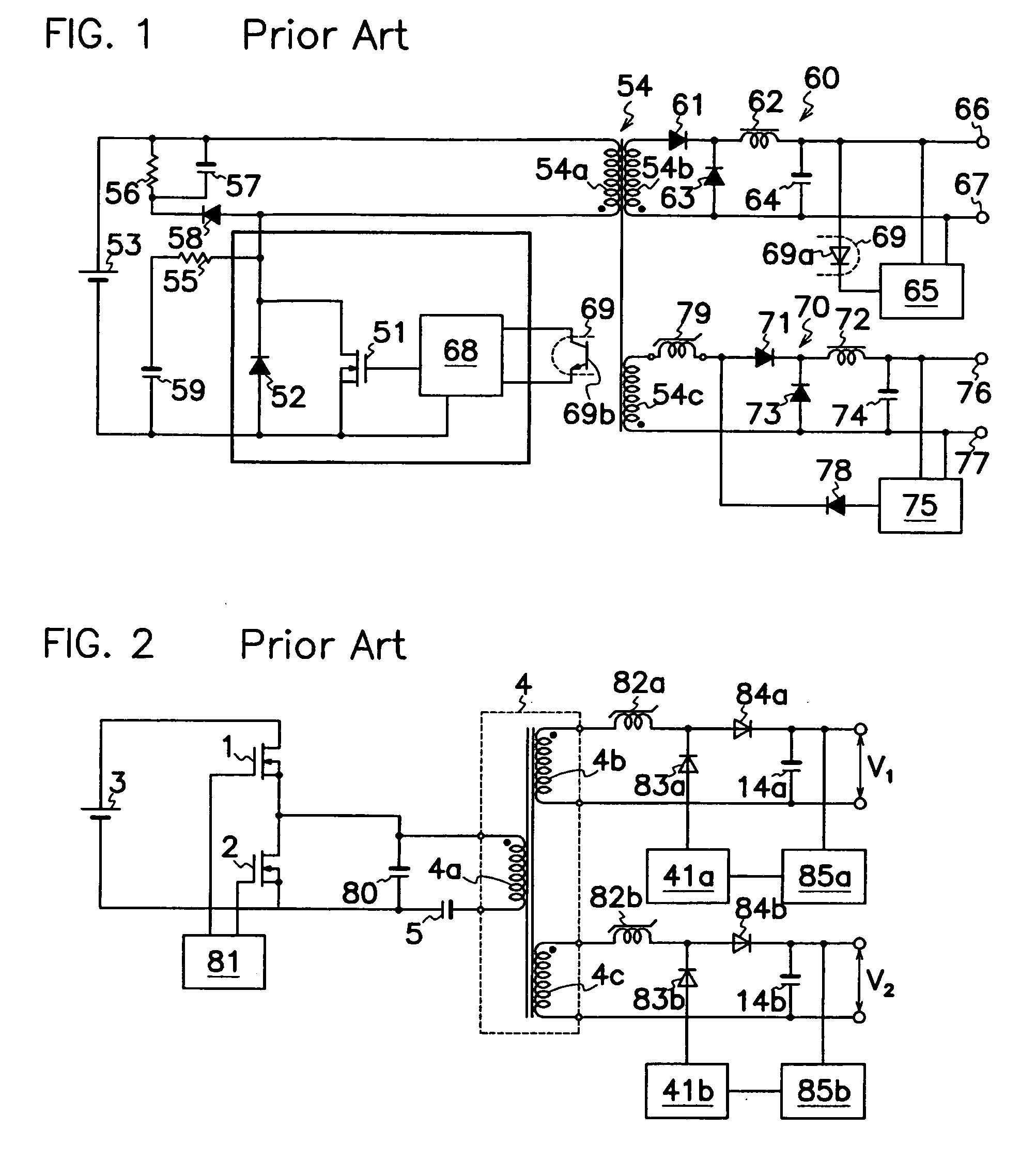
a dc-dc converter and multi-output technology, applied in the direction of dc-dc conversion, power conversion systems, climate sustainability, etc., can solve the problems of defective dc-dc converters of forward type shown in fig. 1 and insufficient supply of electric power

Inactive Publication Date: 2006-08-03
SANKEN ELECTRIC CO LTD
View PDF5 Cites 20 Cited by
  • Summary
  • Abstract
  • Description
  • Claims
  • Application Information

AI Technical Summary

Benefits of technology

[0010] The DC-DC converter of multi-output type according to the present invention, comprises first and second switching elements (1, 2) connected in series to a DC power source (3); a series circuit of a capacitor (5), a current resonance inductance (6) and a primary winding (4a) of a transformer (4) connected in series between a junction of first and second switching elements (1, 2) and DC power source (3); and a control circuit (8) for alternately turning first and second switching elements (1, 2) on and off to produce a plurality of DC outputs from plural secondary windings (4b to 4d) of transformer (4) each through rectifying smoother (12, 22, 32). Duty ratio of first and second switching elements (1, 2) is adjusted to control a first DC output produced from a first secondary winding (4b). Also, at least one magnetic amplifier (21, 31) is connected in series between each of second or more secondary windings and related rectifying smoother (22, 32) to adjust reset current to the magnetic amplifier (21, 31), thereby controlling DC-output from the second or more secondary windings (4c, 4d). The period of producing DC outputs from secondary windings (4b, 4c, 4d) from magnetic energy accumulated in transformer (4) is unchanged and determined by resonance frequency by resonance capacitor (5) and current resonance inductance (6). Accordingly, when first and second switching elements (1, 2) are turned on and off under control based on output level from first primary winding (4b), pulses determined by resonance frequency resulted from resonance capacitor (5) and current resonance inductance (6) are inevitably supplied to the magnetic amplifier (21, 31) connected to second or more secondary windings (4c, 4d) for stabilized control of the magnetic amplifier (21, 31). Thus, the instant invention enables the magnetic amplifier (21, 31) to perform its well-balanced operation to take a stable DC output out of second or more than two secondary windings (4c, 4d).

Problems solved by technology

Accordingly, DC-DC converter of forward type shown in FIG. 1 is defective in that it cannot supply sufficient electric power to loads during the light load period for the foregoing reason.

Method used


Image

  • Resonant DC-DC converter of multi-output type
  • Resonant DC-DC converter of multi-output type
  • Resonant DC-DC converter of multi-output type

Examples


Embodiment Construction

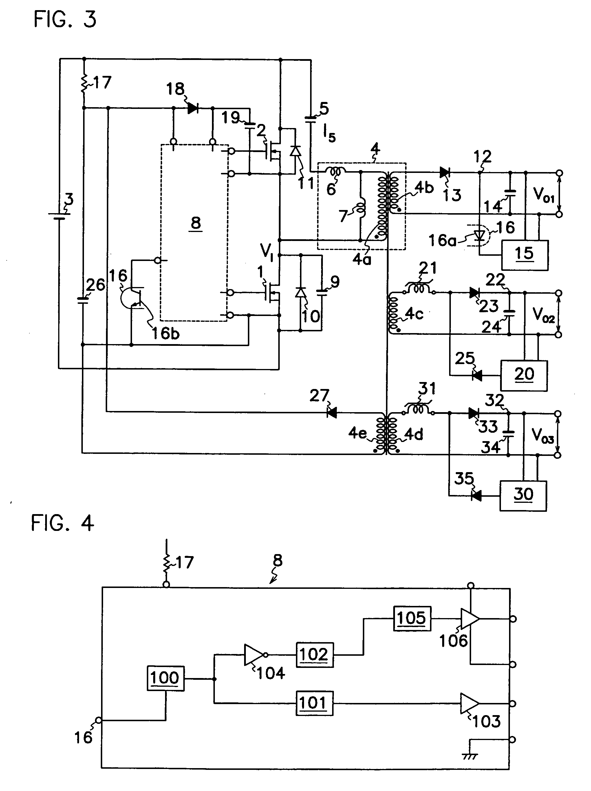
[0023] Embodiments of the resonant DC-DC converter of multi-output type according to the present invention will be described hereinafter in connection with FIGS. 3 to 11 of the drawings. Same reference symbols as those shown in FIGS. 1 and 2 are applied to similar portions in these drawings, omitting explanation therefor.

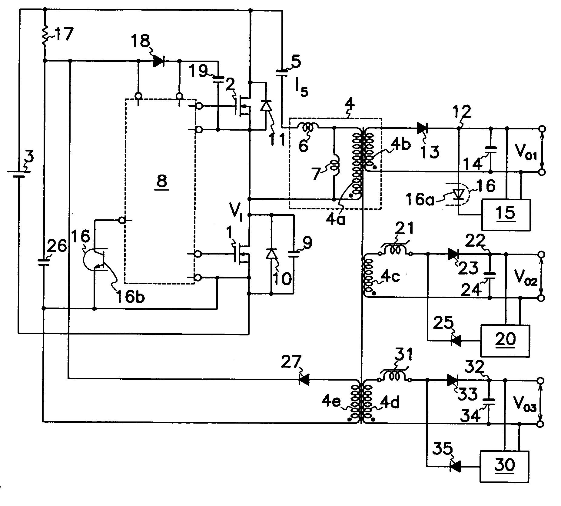
[0024] As shown in FIG. 3, the DC-DC converter of multi-output type according to the present invention, comprises first and second MOS-FETs 1 and 2 as first and second switching elements connected in series to a DC power source 3; a series circuit of a capacitor 5, a current resonance inductance 6 and a primary winding 4a of a transformer 4 connected in series between a junction of first and second MOS-FETs 1 and 2 and DC power source 3; an excitation inductance 7 connected in parallel to primary winding 4a of transformer 4; and a control circuit 8 for alternately turning first and second MOS-FETs 1 and 2 on and off. A parasitic capacitor 9 and a parasitic diode 10...


PUM


Abstract

A DC-DC converter of multi-output type is provided wherein first and second MOS-FETs 1 and 2 are alternately turned on and off to take a plurality of DC outputs out of a plurality of secondary windings 4b, 4c and 4d of a transformer 4 through related rectifying smoothers 12, 22 and 32. A first DC output from first secondary winding 4b is controlled by adjusting a duty ratio of first and second MOS-FETs 1 and 2. At least one magnetic amplifier 21, 31 is connected in series between each of second or more secondary windings 4c and 4d and related rectifying smoother 22 and 32 to adjust reset current to the magnetic amplifier 21, 31, thereby generating stabilized DC-outputs VO2 and VO3 from the second or more secondary windings 4c, 4d.

Description

TECHNICAL FIELD [0001] This invention relates to a DC-DC converter, in particular, a resonant DC-DC converter of multi-output type capable of producing stabilized DC output powers. BACKGROUND OF THE INVENTION [0002]FIG. 1 shows a prior art DC-DC converter of forward type which comprises a MOS-FET 51 as a switching element connected in series to a DC power source 53 and a primary winding 54a of a transformer 54; a control circuit 68 for supplying drive signals to a control or gate terminal of MOS-FET 51, a first rectifying smoother 60 connected to a first secondary winding 54b of transformer 54; and a second rectifying smoother 70 connected to a second secondary winding 54c of transformer 54. A parasitic diode 52 is connected in parallel to MOS-FET 51 which also is connected in parallel to a series circuit of a resistor 55 and a capacitor 59. Another series circuit of a rectifying diode 58 and a resistor 56 is connected in parallel to primary winding 54a, and a capacitor 57 is connec...

Claims


Application Information

Patent Timeline
Patent Type & Authority Applications(United States)
IPC IPC(8): H02J3/00
CPCH02M3/33523H02M3/337Y02B70/1433Y02B70/10H02M3/33571H02M3/01
Inventor USUI, HIROSHI
Owner SANKEN ELECTRIC CO LTD
Why Eureka
Try Eureka