Processing of uplink data in a communications system
a technology of communication system and data processing, applied in the field of processing data in the communication system, can solve problems such as degrading the end user experience and interrupting the connection in non-cellular communication system
- Summary
- Abstract
- Description
- Claims
- Application Information
AI Technical Summary
Benefits of technology
Problems solved by technology
Method used
Image
Examples
first embodiment
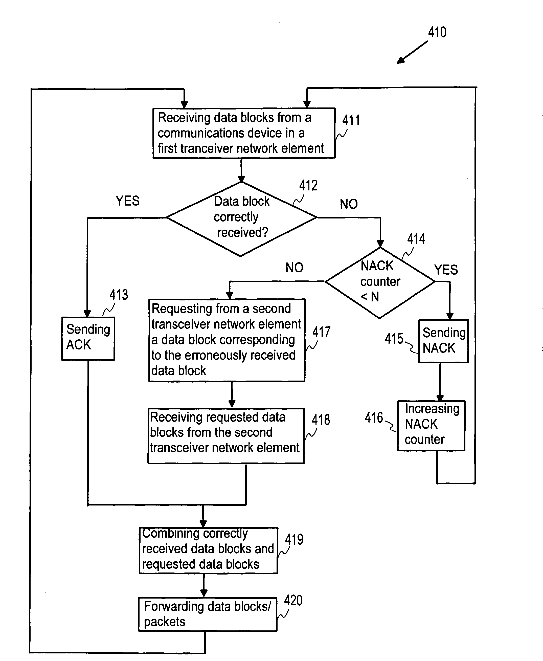
[0150]FIG. 4a shows schematically functionality in accordance with the invention. A communications device 101 is sending data in the uplink direction. A first transceiver network element 401 and a second transceiver network element 402 are receiving data blocks and acknowledging successful receipt of the data blocks. As specific example, the data blocks may be sent on the HSUPA channel and HARQ may be used for acknowledging receipt of data blocks or the data blocks may be sent on a 3GPP Release 99 channel with link layer retransmissions. In principle, the communications device 101 should not retransmit a data block which is acknowledged by at least one transceiver network element. Both the first and the second transceiver network elements 401, 402 may send power control commands to the communications device 101. The communications device 101 adjusts the transmission power of the data blocks in accordance with the power control commands it receives.
[0151] The first transceiver networ...
second embodiment
[0161] In a first alternative of the invention, the serving transceiver network element is typically changed at the end of a data packet, a data packet consisting of a plurality of data blocks (excluding, for example, header information). This way complete data packets may be forwarded from the serving transceiver network element further to the communications system. If a need to change the serving transceiver network element is noticed when only some data blocks relating to a data packet have been received, the already received data blocks may be transmitted from the current serving transceiver network element to the new serving transceiver network element. If the communications system (the serving transceiver network element) decides to change the serving transceiver network element, no modifications are typically needed in the communications device.
[0162] It is appreciated that the change of the serving transceiver network element may be performed each time an end of a data packe...
third embodiment
[0175]FIG. 6a shows schematically functionality in accordance with the invention. The serving transceiver network element 601 receives data blocks sent by the communications device 101 and sends acknowledgement information and typically also power control commands accordingly to the communications device 101. The second transceiver network element 602 is synchronized with the physical transmission channel relating to the data blocks sent by the communications device. The second transceiver network element 602 determines the quality of the uplink radio path and reports the quality to the serving transceiver network element 601. The communications device 101 in FIG. 6a may believe that it is performing a basic hard handover, whereas the communication system is performing a prepared hard handover. As in connection with FIGS. 4a and 5a there may be one or more second transceiver network elements 602.
[0176] Information about the quality of the uplink radio path is typically determined ba...
PUM
 Abstract
Description
Claims
Application Information
 - R&D
- Intellectual Property
- Life Sciences
- Materials
- Tech Scout
- Unparalleled Data Quality
- Higher Quality Content
- 60% Fewer Hallucinations
Browse by: Latest US Patents, China's latest patents, Technical Efficacy Thesaurus, Application Domain, Technology Topic, Popular Technical Reports.
© 2025 PatSnap. All rights reserved.Legal|Privacy policy|Modern Slavery Act Transparency Statement|Sitemap|About US| Contact US: help@patsnap.com


