Hydraulic transmission vehicle

a transmission vehicle and hydraulic technology, applied in fluid gearings, transportation and packaging, gearing, etc., can solve the problems of changing the hst speed change ratio, unable to obtain the speeding up and slowing of the vehicle, and no conventional transmission which controls the output of the hs

Inactive Publication Date: 2006-08-03
YANMAR AGRICULT EQUIP CO LTD +1
View PDF16 Cites 31 Cited by
  • Summary
  • Abstract
  • Description
  • Claims
  • Application Information

AI Technical Summary

Benefits of technology

[0020] A first object of the present invention is to provide a vehicle having an HST whose output / input rotation speed ratio is changeable by an electronic actuator, wherein a load on the HST is detected effectively and the speed change ratio of the HST is set to correspond to the load.

Problems solved by technology

However, there is no conventional transmission which controls output of the HST with considering load applied to the HST itself.
Therefore, unless the load applied to the HST is considered in the controlling, desired vehicle speed, speeding up and slowdown of the vehicle may not be obtained.
Providing a detection mean of rising degree of oil pressure in the HST is handicapped in complexity of structure, cost and compactness of the HST, thereby being inexpedient.
Therefore, with regard to the speeding up operation requiring switching between the HST mode and the HMT mode, the change of the HST speed change ratio at the time of switching the mode becomes larger, whereby shock attendant upon the switch of the mode becomes larger.
Each field where the tractor performs rotary cultivation is not uniform in conditions such as hardness and viscosity, so that, while the vehicle advancing, the rotary cultivator passes one area requiring careful cultivation and another area which can be cultivated comparatively easily.
However, the operation of changing cultivation speed while checking the field condition is a burden to the operator and disturbs his / her concentration on steering operation.
Accordingly, cultivation speed can't be increased at the time of turning, thereby taking time.
However, the conventional working vehicle such as the tractor may be stopped by actuating the parking brake without turning the traveling transmission into neutral, or may be started while the parking brake is still applied, thereby causing abrasion of a brake disk.

Method used


Image

  • Hydraulic transmission vehicle
  • Hydraulic transmission vehicle
  • Hydraulic transmission vehicle

Examples


Embodiment Construction

[0107] The invention will be described in detail according to attached drawings.

[1. Entire Construction of Vehicle]

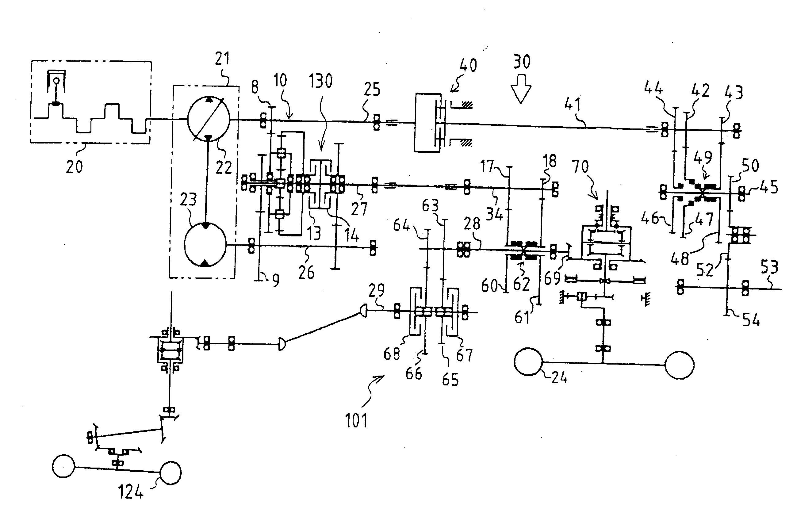
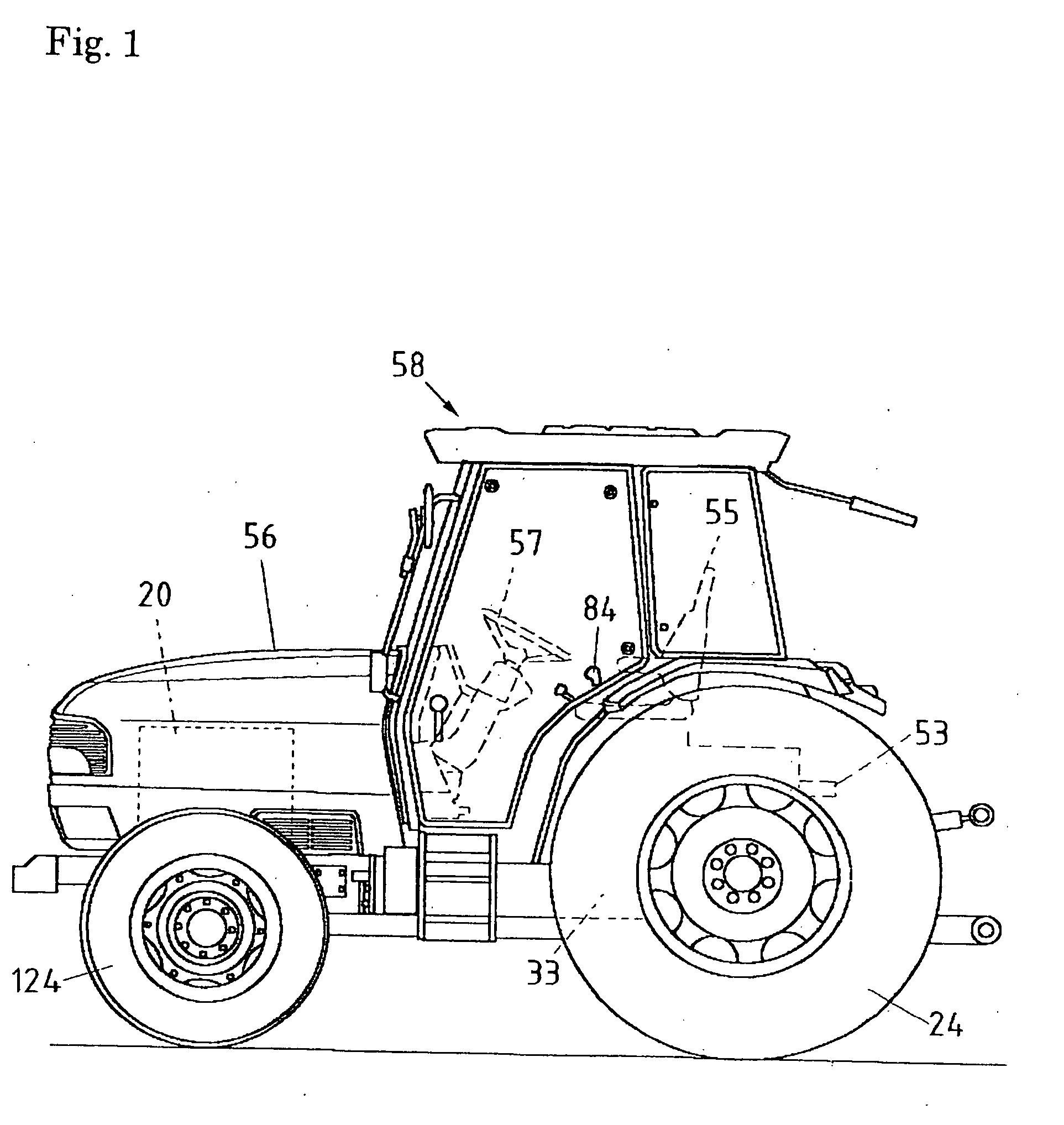
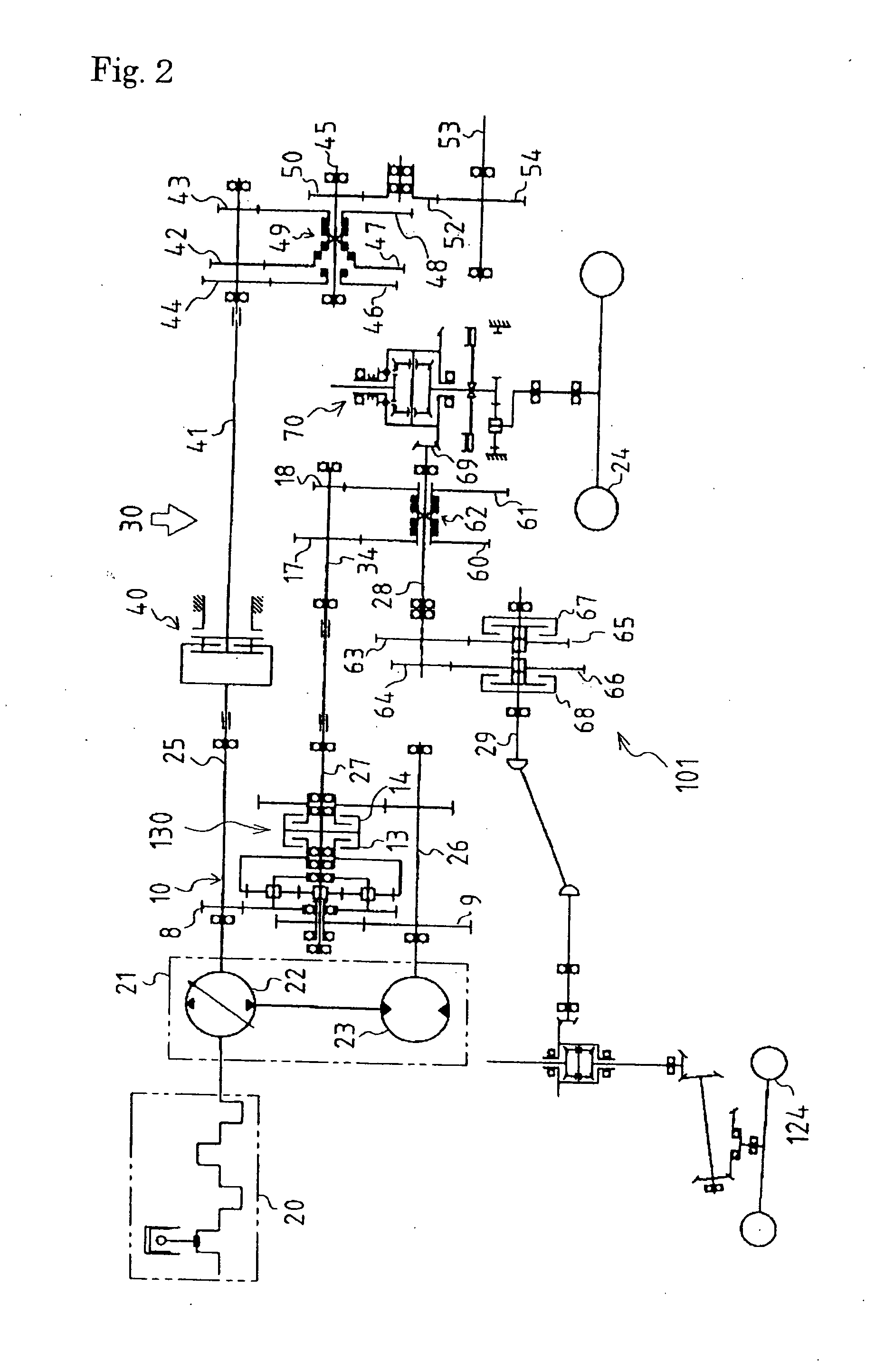
[0108] Explanation will be given on an entire construction of a tractor as an embodiment of a vehicle equipped with an HST controlled by the present invention in accordance with FIG. 1 and others.

[0109] Front wheels 124 and rear wheels 24 are supported by front and rear end portions of the vehicle, respectively. An engine 20 is disposed in a bonnet 56 disposed at the front portion of the vehicle. A steering wheel 57 is provided behind the bonnet, and a seat 55 is disposed behind the steering wheel 57. A main speed change lever 84, a sub speed change switch 87, a lever for adjusting height of a working machine, and the like project from side portions of the seat 55. Pedals, such as a brake pedal, a main clutch pedal and a differential lock pedal, are disposed on a floor in lower front of the seat 55. The steering wheel 57, the seat 55, the levers and the pedals are di...


PUM


Abstract

A hydraulic transmission (21) has an electric actuator (86) for changing its output / input rotation speed ratio. A controller (90) of the actuator memorizes a command current value to the actuator supposing that load is not applied on the hydraulic transmission, and calculates a value of load applied on the hydraulic transmission by calculating a difference between an actual command current value to the actuator and the memorized command current value. A command current value is compensated based on the value of load, and the actuator receives feedback to be controlled. A vehicle may have a differential mechanism (10), which combines rotation powers on input side and output side of the hydraulic transmission. A detector (82) detects rotation speed of a main speed change output shaft (27) serving as an output shaft of the differential mechanism. If the detected rotation speed differs from target rotation speed of the shaft (27) determined based on operation of a speed change operation tool, the actuator is forcedly controlled. This difference is supposed to be caused by load applied on the hydraulic transmission, whereby the load is calculated.

Description

CROSS-REFERENCE TO RELATED APPLICATIONS [0001] This application is a Divisional of U.S. application Ser. No. 10 / 805,561; filed Mar. 22, 2004, the entire disclosure of which is incorporated herein by reference.BACKGROUND OF THE INVENTION [0002] 1. Field of the Invention [0003] The present invention relates to control of a hydraulic stepless transmission (hereinafter, referred to as HST) equipped on a vehicle. [0004] 2. Background Art [0005] Conventionally, there is a well-known HST as a transmission for a vehicle, especially for a working vehicle such as a tractor. The International Publication WO00 / 25041 and the Japanese Patent Laid Open Gazette 2001-108061 indicate a hydro mechanical transmission (hereinafter, referred to as HMT) having a differential mechanism driven by rotation difference between input and output of the HST (for example, a planetary gear mechanism) as the transmission for a working vehicle. With regard to this transmission, at the time of traveling forward in low...

Claims


Application Information

Patent Timeline
Patent Type & Authority Applications(United States)
IPC IPC(8): F16H61/38B60W10/10B60W30/18F16H47/04F16H59/16F16H59/22F16H59/46F16H59/54F16H61/42F16H61/439F16H61/46F16H61/465F16H61/468F16H61/47
CPCB60W10/103Y10T477/688B60W2510/0642B60W2510/186B60Y2200/22B60Y2200/221F16H47/04F16H59/16F16H59/22F16H59/46F16H59/54F16H61/439F16H61/46F16H61/465F16H61/468F16H61/47F16H2037/088F16H2037/0886Y02T10/56F16H2061/168F16H2059/148Y10T477/631Y10T477/636B60W30/1888Y02T10/84Y02T10/40
Inventor ISHIBASHI, FUMIOKUBOTA, YUKIONOMA, YASUOKURODA, AKIFUMI
Owner YANMAR AGRICULT EQUIP CO LTD
Why Eureka
Try Eureka