Ultrasonic probe

a technology of ultrasonic elements and probes, applied in the field of ultrasonic probes, can solve the problems of complicated control of the origin return delaying the origin return time, and inability to accurately detect the position of the ultrasonic element at the time of turning on the switch with respect to the ultrasonic probe, etc., to achieve the effect of easily and quickly controlling the origin return of an ultrasonic elemen

Inactive Publication Date: 2006-08-03
KONICA MINOLTA INC
View PDF11 Cites 173 Cited by
  • Summary
  • Abstract
  • Description
  • Claims
  • Application Information

AI Technical Summary

Benefits of technology

[0006] The object of the present invention is to provide an ultrasonic probe w

Problems solved by technology

In the conventional ultrasonic probe, however, the detector detects only the number of light reception counts, thus it has been impossible to detect accurately an oscillation origin or the position of the ultrasonic eleme

Method used


Image

  • Ultrasonic probe
  • Ultrasonic probe
  • Ultrasonic probe

Examples


embodiment 1

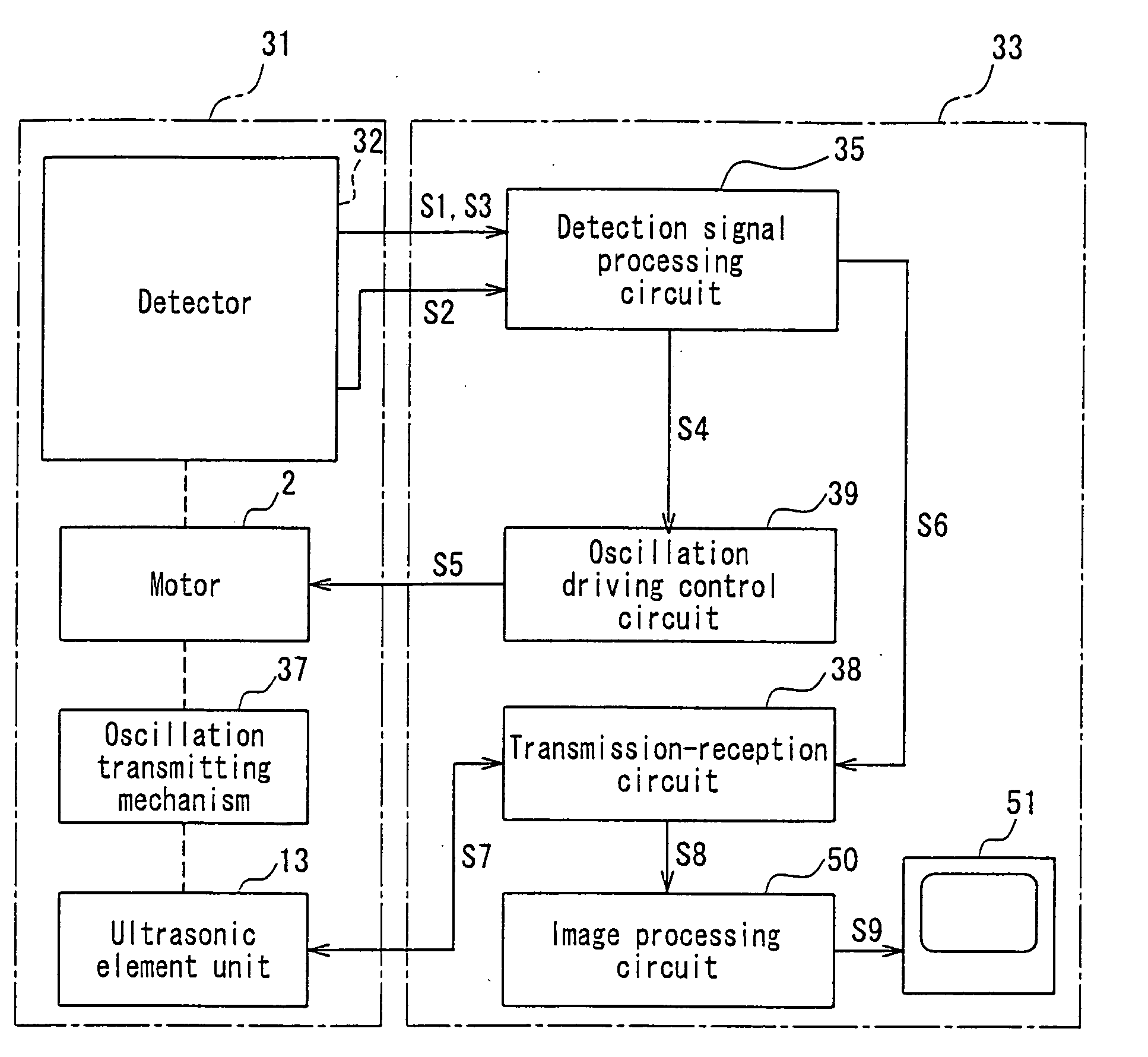
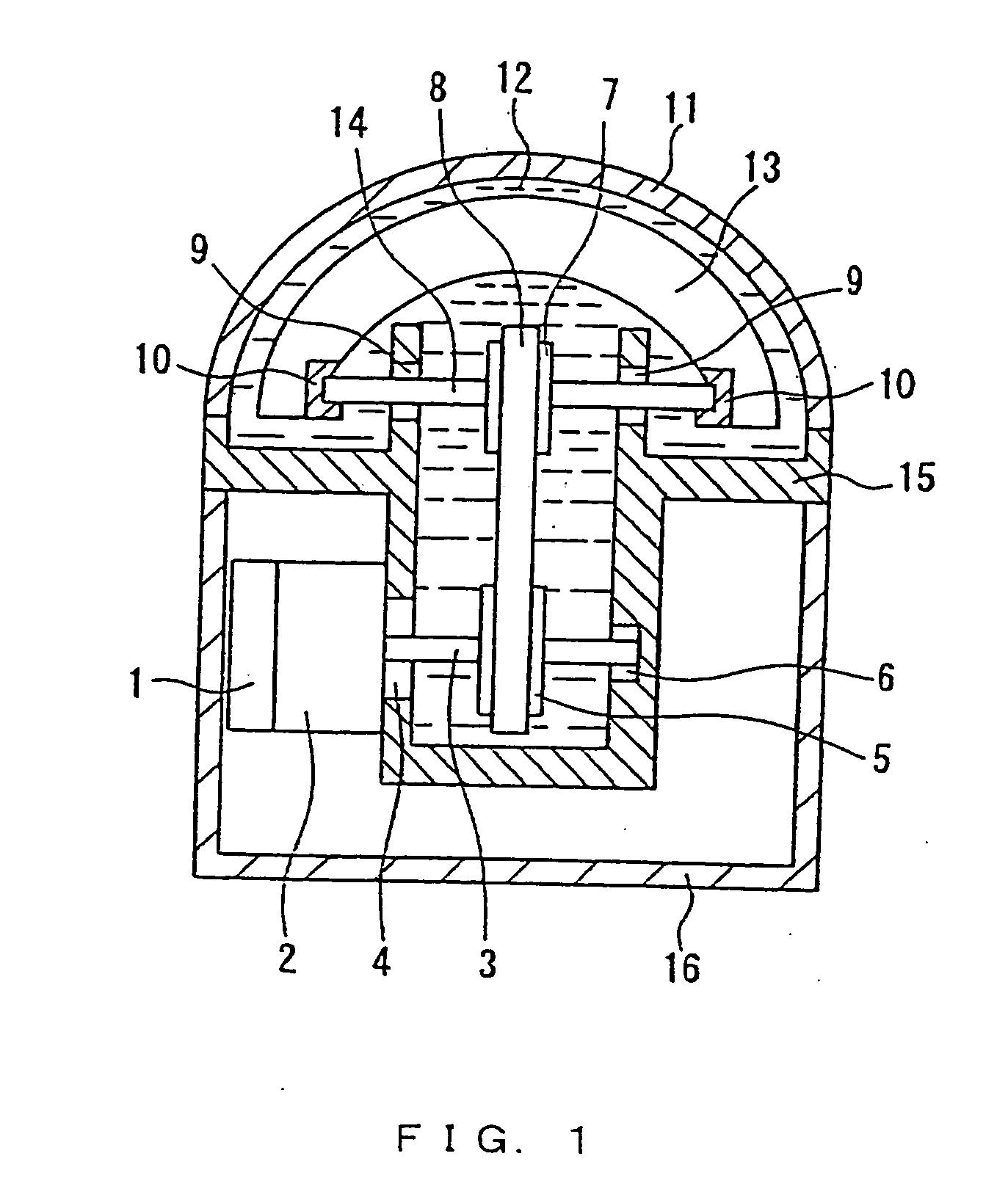
[0023]FIG. 1 is a cross-sectional view showing an example of the ultrasonic probe according to Embodiment 1 of the present invention. In the ultrasonic probe, a medium chamber is formed by connecting a window 11 to a frame 15. The medium chamber is filled with a degassed acoustical coupling medium 12. In the medium chamber, an ultrasonic element unit 13 formed by aligning plural oscillators is contained. The ultrasonic element unit 13 is fixed to an oscillation axis 14 by an oscillation axis holder 10, and the oscillation axis 14 is supported rotatably by a bearing 9 provided to the frame 15.

[0024] By fixing the oscillation axis 14 directly to the ultrasonic element unit 13 as mentioned above, the radius of the oscillation can be decreased, therefore, the size of the window 11 can be decreased relatively to the oscillation scanning angle of the ultrasonic element unit 13, and the moment of inertia with respect to the oscillation axis 14 can be reduced, thus realizing the reduction ...

embodiment 2

[0046]FIG. 5 is a cross-sectional view showing an example of the structure of the ultrasonic probe according to Embodiment 2 of the present invention. A detector in the present invention is composed of an oscillation angle detector and an oscillation origin detector which are separated from each other. In FIG. 5, the same parts as in FIG. 1 are assigned with the same reference numerals, and the description about the parts are omitted.

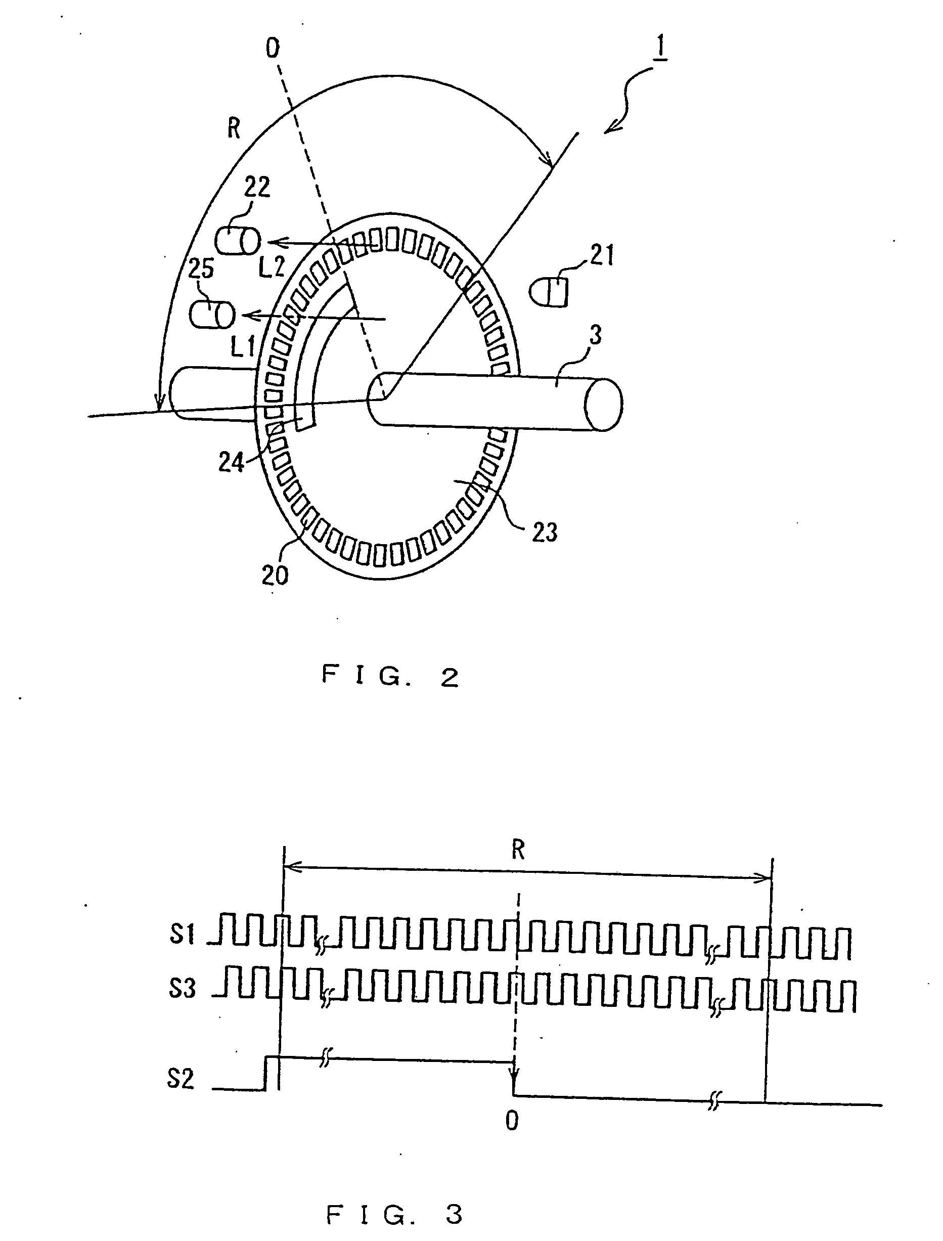
[0047] An origin detector 43 is for detecting the position and the oscillation origin of the ultrasonic element unit. This is structured as an optical rotary encoder, and attached to an output axis of a motor 2. The origin detector 43 can have the same structure as the detector illustrated in FIG. 2, except that the second slits 20 and the second photodetector 22 are omitted. The detection operation is substantially the same as that of the second slits in Embodiment 1.

[0048] An oscillation angle detector 40 is for detecting the oscillation angle of th...


PUM


Abstract

The ultrasonic probe of the present invention includes an ultrasonic element unit for transmitting and receiving ultrasonic waves, an oscillation mechanism for causing oscillation to the ultrasonic element unit and a detector for detecting the oscillation of the ultrasonic element unit. The detector detects the oscillation angle and the oscillation origin of the ultrasonic element unit, and when the oscillation range of the ultrasonic element unit is divided at its oscillation origin into two regions of a positive region and a negative region, the detector detects in which area the ultrasonic element unit is located. In use of the ultrasonic probe, a control of origin return for returning the ultrasonic element unit to its oscillation origin is performed on the basis of the result of the detection by the detector.

Description

TECHNICAL FIELD [0001] The present invention relates to an ultrasonic probe, more specifically, an ultrasonic probe which transmits and receives ultrasonic waves with respect to a subject, changing the surface to be scanned by the mechanical oscillation of an ultrasonic element. BACKGROUND ART [0002] In a medical field, ultrasonic diagnostic apparatuses are widely used, such an apparatus transmits and receives ultrasonic waves by using an ultrasonic probe with respect to a subject, so that it obtains information about the respective parts of the subject, depending on the acoustic characteristics of the parts. In the ultrasonic diagnostic apparatus, a transducer array as an ultrasonic element for transmitting and receiving ultrasonic waves is used, and this transducer array is oscillated mechanically to change the surface to be scanned with the ultrasonic waves, thereby obtaining three-dimensional information of the subject. [0003] The probe used in such an ultrasonic diagnostic appa...

Claims


Application Information

Patent Timeline
IPC IPC(8): A61B8/14A61B8/06A61B8/00G01D5/14G01D5/347G01S15/89G10K11/35H03M1/30
CPCA61B8/4281A61B8/4461G01D5/145G01D5/3473G01S15/894G10K11/355H03M1/308A61B8/00
Inventor IRIOKA, KAZUYOSHIOOKAWA, EIICHIKOIZUMI, JUNHASEGAWA, SHIGEYOSHI
Owner KONICA MINOLTA INC
Why Eureka
Try Eureka