
CPR performance reporting system

a defibrillator and data reporting technology, applied in the field of defibrillator systems, can solve the problems of reducing the amount of blood pumped to the body, affecting the normal or sinus heartbeat rhythm, and ineffective pumping of the ventricular muscles,

Inactive Publication Date: 2006-08-03
MEDTRONIC PHYSIO CONTROL
View PDF8 Cites 179 Cited by
  • Summary
  • Abstract
  • Description
  • Claims
  • Application Information

AI Technical Summary

Benefits of technology

[0010] A method for assessing CPR performed during at least one resuscitation event includes obtaining a data set during each of the at least one resuscitation, each data set including data relating to the performance of chest compressions, or ventilations, or both,...

Problems solved by technology

In certain circumstances, the normal or sinus heartbeat rhythm may be adversely affected as a result of some type of malfunction in the heart's electrical control system.
When this type of malfunction occurs, an irregular heartbeat may result, causing the ventricular muscles to pump ineffectively, thus reducing the amount of blood pumped to the body.
VF rarely terminates spontaneously, and is therefore a leading cause of sudden cardiac arrest.
Recent statistical studies suggest that the amount of time devoted to CPR during a typical resuscitation event may be less than optimal in real world situations.
Although some of the defibrillator usage time is necessarily occupied by rhythm analysis and defibrillation functions—which in most cases preclude the simultaneous delivery of CPR—there may be an undesirable amount of “wasted” time during which neither the defibrillator device nor the caregiver are actively administering treatment to the patient.

Method used


Image

  • CPR performance reporting system
  • CPR performance reporting system
  • CPR performance reporting system

Examples


Embodiment Construction

[0024] The following detailed description is merely exemplary in nature and is not intended to limit the invention or the application and uses of the invention. Furthermore, there is no intention to be bound by any expressed or implied theory presented in the preceding technical field, background, brief summary or the following detailed description.

[0025] Aspects of the invention may be described herein in terms of functional and / or logical block components and various processing steps. It should be appreciated that such block components may be realized by any number of hardware, software, and / or firmware components configured to perform the specified functions. For example, an embodiment of the invention may employ various integrated circuit components, e.g., memory elements, digital signal processing elements, logic elements, look-up tables, or the like, which may carry out a variety of functions under the control of one or more microprocessors or other control devices. In additi...


PUM


Abstract

A method for assessing CPR performed during at least one resuscitation event includes obtaining a data set during each of the at least one resuscitation events, each data set including data characterizing the performance of chest compressions or ventilations, or both, on the patient during the at least one resuscitation event; processing the data set to determine a value of at least one parameter of the performance; and displaying a graphical representation of the at least one parameter. A graphical representation of a desired value or range of values of the at least one parameter may be displayed in a position for visual comparison with the determined value. A method for presenting information on a sequence of events during a resuscitation event includes: obtaining data on the sequence and timing of chest compression and lung ventilations from a defibrillator; and displaying symbols for chest compressions and lung ventilations in a linear sequence corresponding to the order in which the compressions and ventilations occurred, the linear distance between successive symbols being proportional to the temporal distance between the corresponding actions.

Description

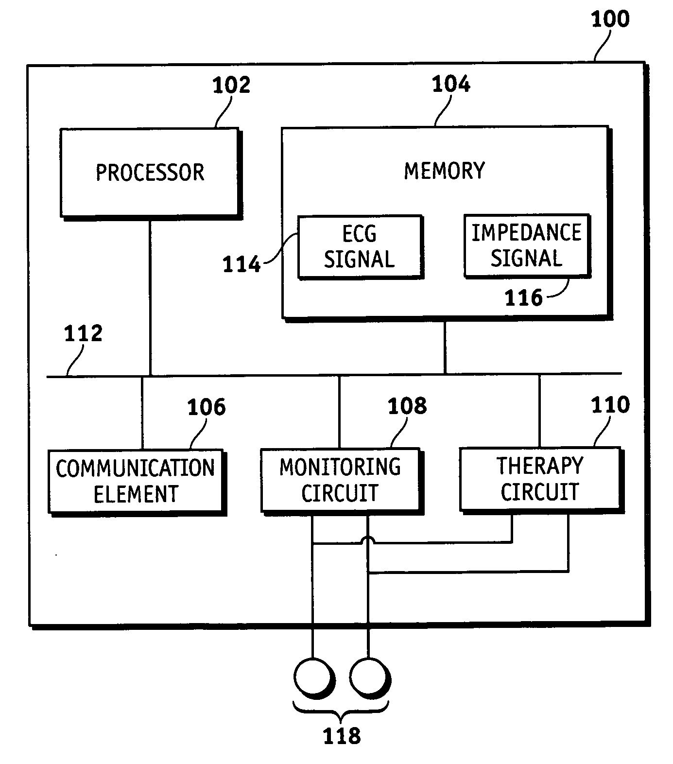
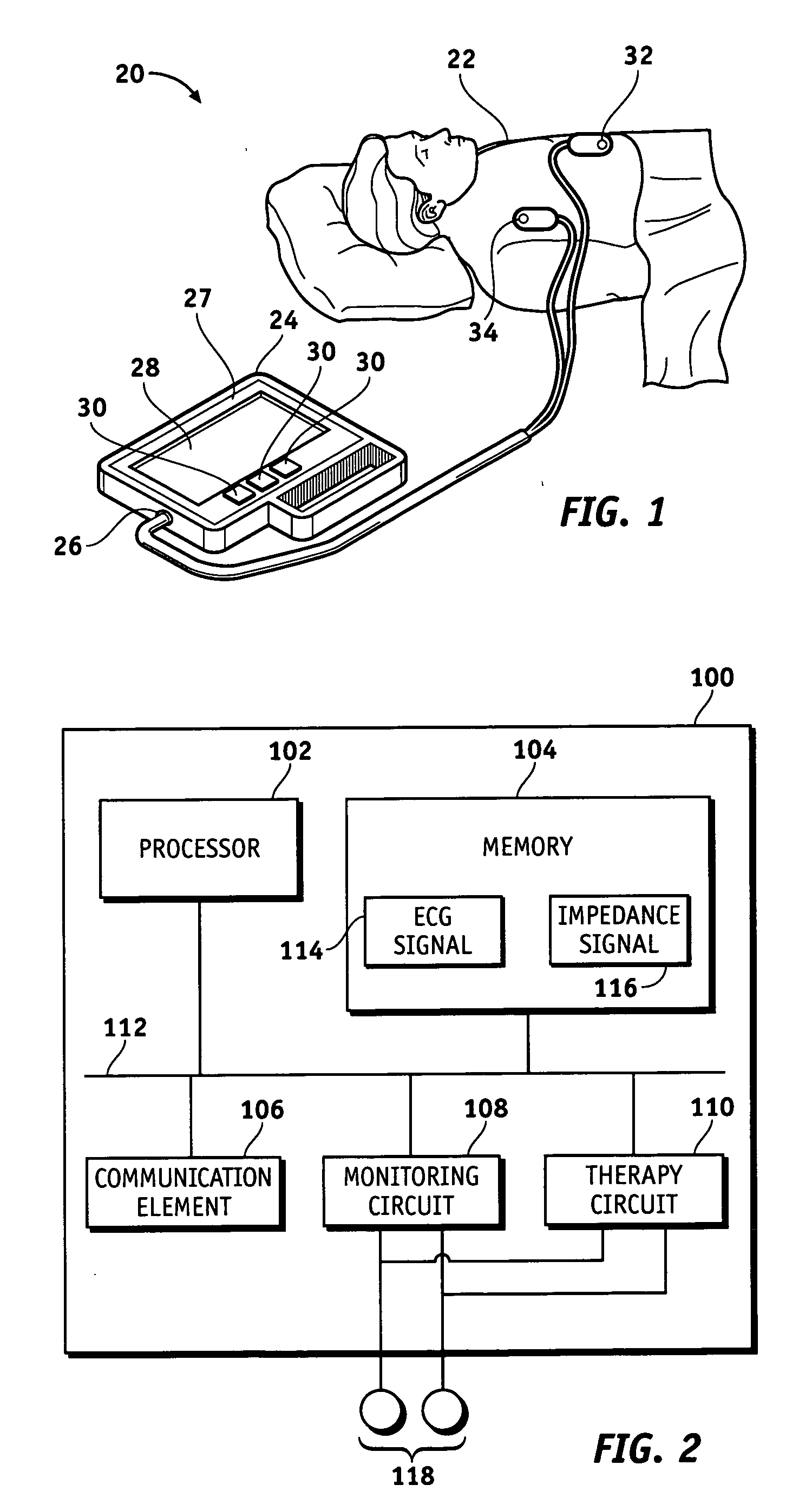
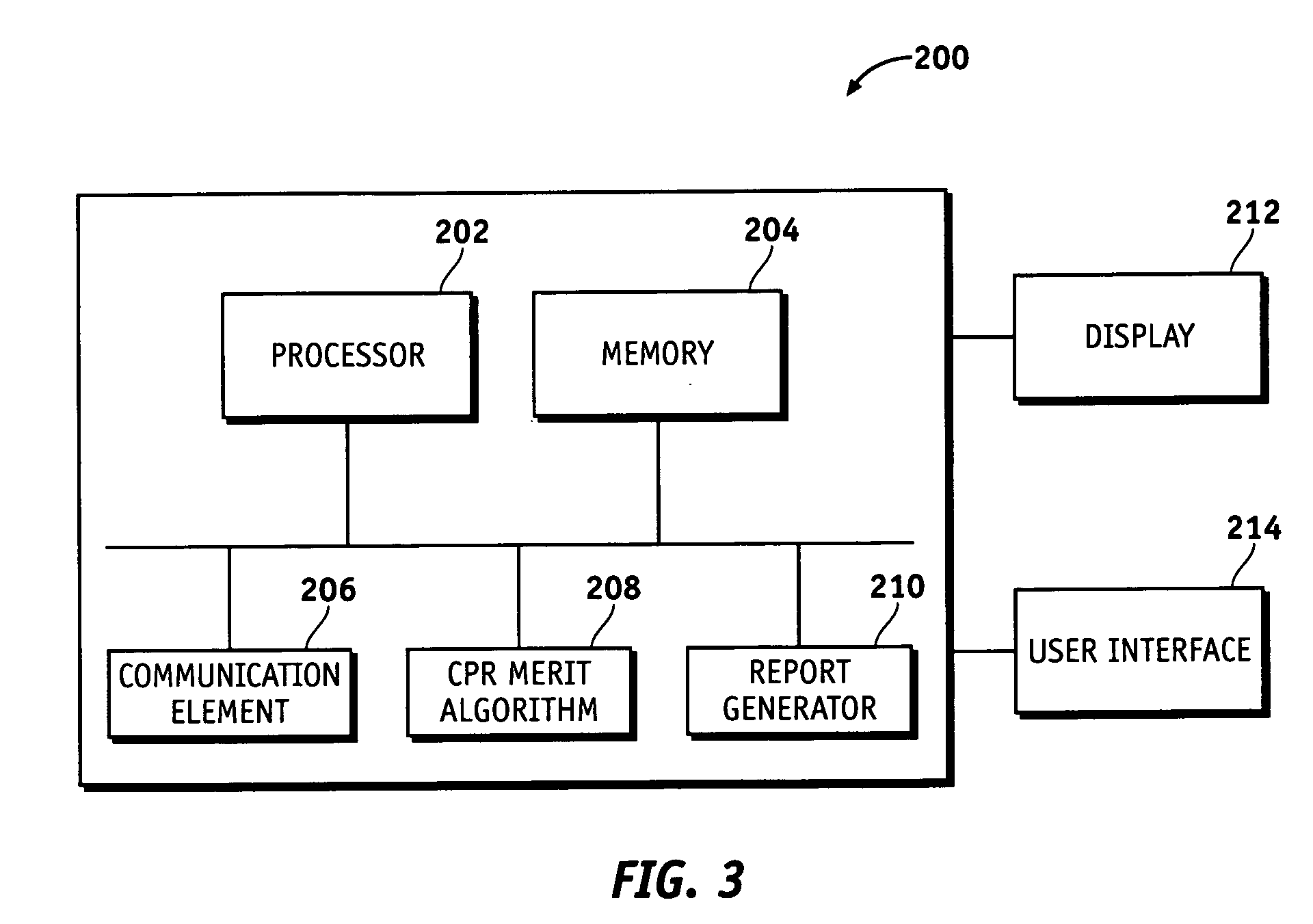
REFERENCE TO RELATED APPLICATION [0001] This application is a continuation in part of U.S. patent application Ser. No. 11 / 048,322, filed on Jan. 31, 2005, which is hereby incorporated by reference herein.TECHNICAL FIELD [0002] The present invention relates generally to defibrillator systems. More particularly, the present invention relates to a data reporting system for a defibrillator system. BACKGROUND [0003] A normal human heart pumping pattern is called a sinus rhythm, and the pattern is regulated by the body's biological pacemaker within the upper right chamber of the heart, which is commonly referred to as the right atrium. This natural pacemaker, which is generally referred to as the sinoatrial (“SA”) node, sends electrical signals to the right and left ventricular muscles in the lower chambers of the heart. The ventricular muscles then implement the pumping action under the control of the SA node. The right ventricular muscle pumps blood to the lungs for oxygenation, and the...

Claims


Application Information

Patent Timeline
IPC IPC(8): A61N1/39
CPCA61B5/0205A61B5/046A61B5/0809A61H31/005A61H2201/5007A61H2201/5043A61N1/39A61N1/3993G09B23/288A61N1/39044A61B5/361
Inventor STICKNEY, RONALD E.WALKER, ROBERT G.
Owner MEDTRONIC PHYSIO CONTROL
Learn More