Upright stand

a technology for uprights and supports, applied in the field of uprights, can solve the problems of not being able to adjust the length of uprights to accommodate the necessary difference, affecting the stability of the uprights, etc., and achieves the effect of quiet and light weight, convenient use, and discharging energy from impa

Inactive Publication Date: 2006-08-10
KEELER KEVIN V
View PDF24 Cites 4 Cited by
  • Summary
  • Abstract
  • Description
  • Claims
  • Application Information

AI Technical Summary

Benefits of technology

[0014] An object of the present invention is to provide a stand that is preferably substantially made of polymeric material or “plastic”, and, therefore, is quiet and lightweight. A further object of the present invention is to provide a stand that may be conveniently used by farriers, horse owners, pet groomers, marksmen, hunters, craftsmen, or other animal caretakers, sportsmen, or workers, for example, who need to support, manipulate, and / or control an object in a safe and preferably quiet manner.
[0015] The stand includes a broad, generally flat base and a support system upending from the base. The support system is preferably adjustable in height and includes an object-receiving platform at its top end. Several object-receiving platforms may be provided that are removable and interchangeable with each other. An especially-preferred object-receiving platform comprises a “cradle” with a sling extending between rigid, non-moving arms, whereby the suspended sling provides stable, but somewhat cushioning, support. The preferred height-adjustment is continuous rather than incremental, and the height-adjustment means preferably is substantially silent and smooth.
[0016] The base and support system preferably are of a composition and configuration that absorb and dissipate energy from impact(s) on the horse hoof or other object being supported by the stand. The preferred all-plastic or substantially-plastic base unit absorbs said energy by virtue of its compressibility, resilience, and / or flexibility, wherein one or more of these three features are present in the preferred rugged and generally rigid base unit only a slight amount but an amount that is effective for shock and sound absorption and dissipation during the intended uses. The preferred shape of the base unit is hollow, and, most preferably, conical and flaring out to a broad base that has a concave bottom surface, wherein this shape also helps dissipate the energy of an impact. When combined with the preferred plastic composition, the preferred shape compresses, flexes, or otherwise resiliently responds to said impact(s) to dampen the force and sound of work being done on the hoof or other object.

Problems solved by technology

This is a precarious, sometimes dangerous position, and always a physically-demanding position.
First, the length of the uprights are not adjustable to accommodate the necessary difference in working height between front and back hooves of a single horse, nor to accommodate different-sized horses.
Second, the hoof cradle construction does not provide any concussion absorption and is prone to the hoof dislodging from the cradle.
Thirdly, the legs and horizontally extending upright (effectively a leg) pose a hazard both to the farrier and to the horse.
The inventor believes that prior art devices would tend to move or make noise in a manner that would upset or frighten the animal.
The inventor believes that prior art devices, which include incremental raising or lowering the upright using a ratchet system, would tend to cause uneven and jerky motion and metallic sounds.
The inventor also believes that pivoting / flexing arms or other moving parts would upset / frightened the animal, especially if the pivoting / flexing occurs in response to the weight of the animal's foot and if it causes the stand to “clamp” the foot / hoof.
Further, the inventor believes that the prior art devices would not adequately absorb and dissipate energy from nailing or other work on a horse hoof or on other objects supported in the stand.

Method used


Image

  • Upright stand
  • Upright stand
  • Upright stand

Examples


Embodiment Construction

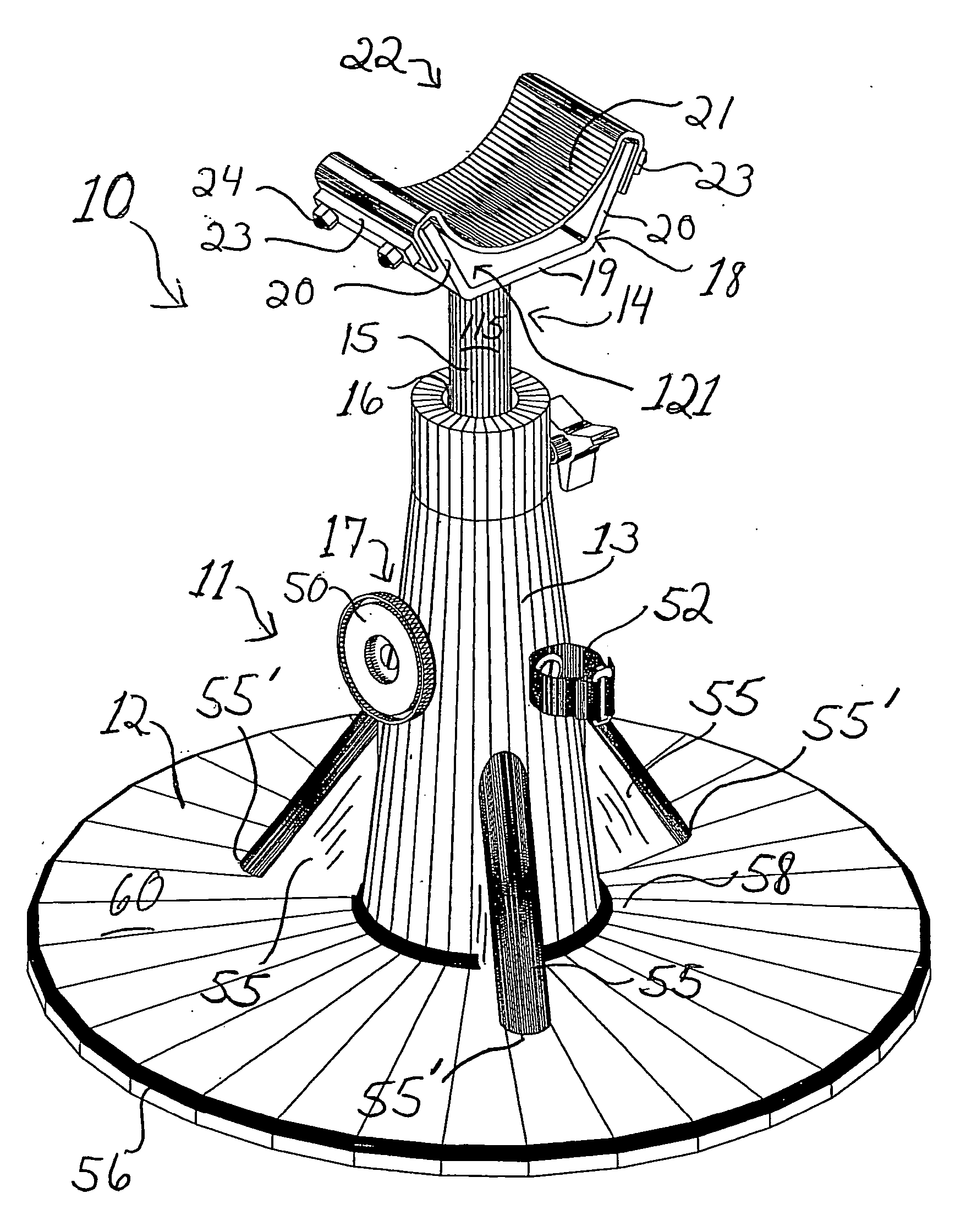
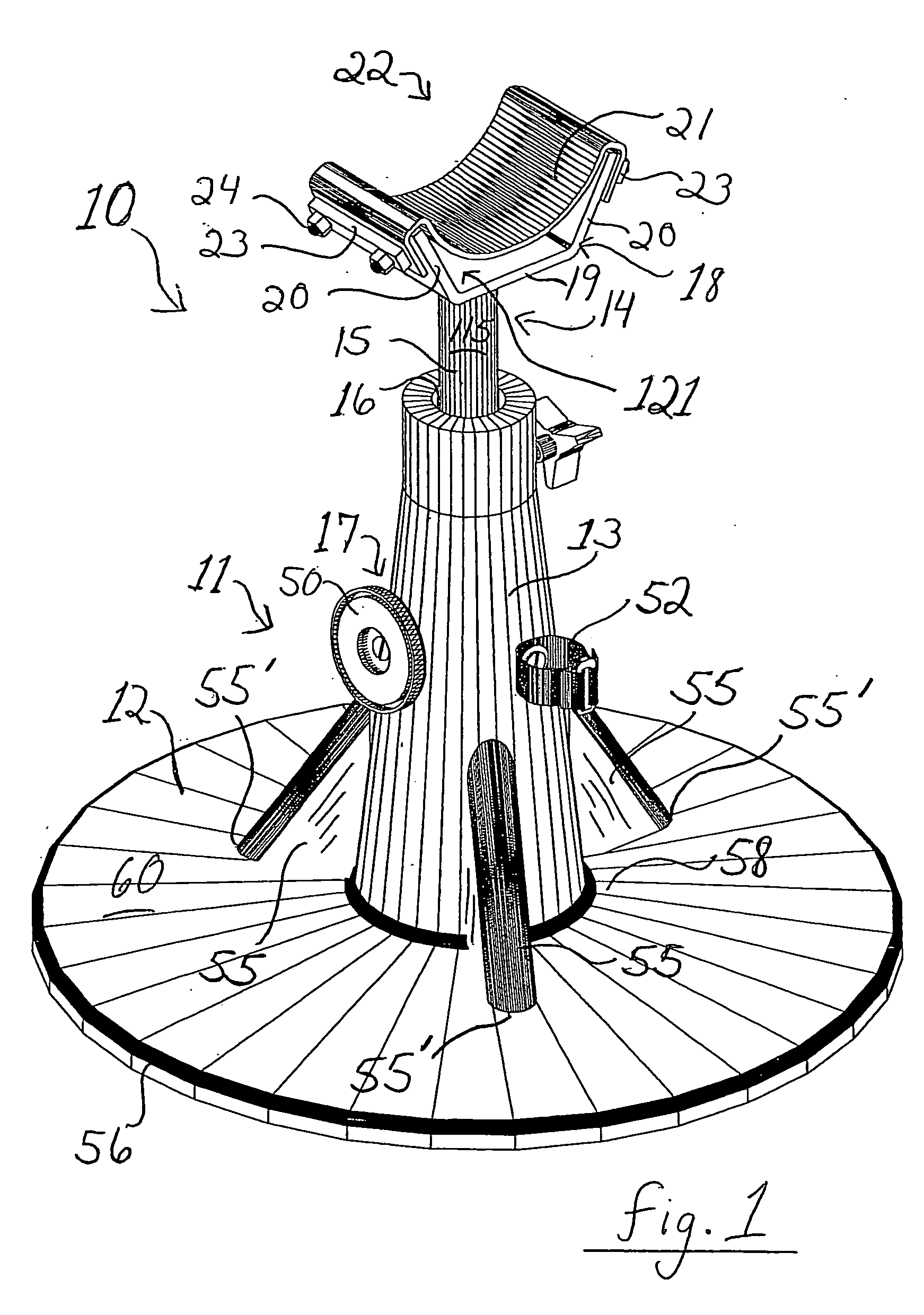
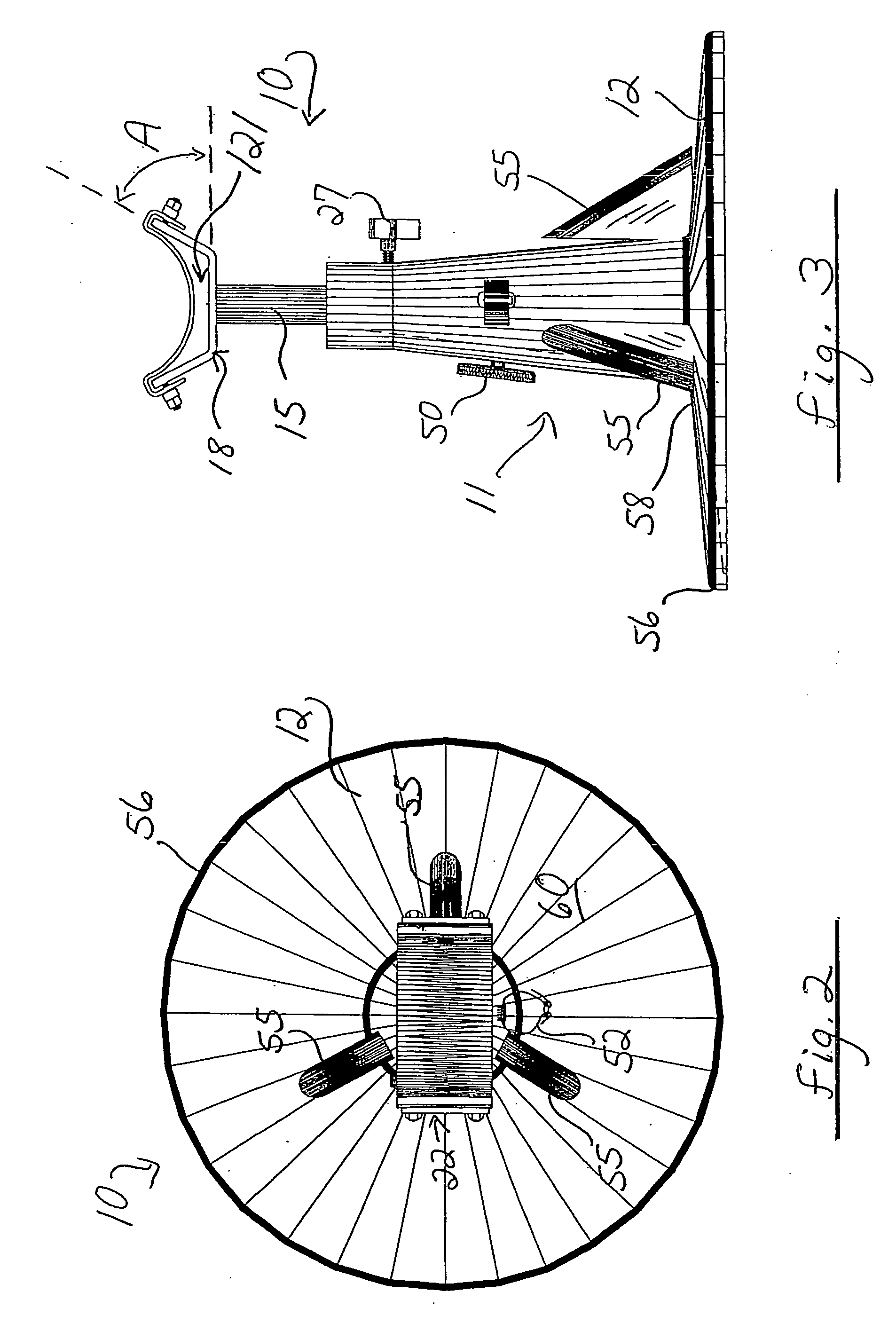
[0026] Some, but not the only, embodiments of the invented stand are shown in detail in the Figures and generally designated as stand 10. Mainly by virtue of its broad base and its being made substantially of plastic, the stand 10 is stable when placed on a surface and also easily moveable to another position or location without significant noise. Of particular note is the quiet, non-frightening sound caused by sliding or otherwise moving the plastic base on a floor, table, or ground, in contrast to the frightening or irritating sound cause by a metal object scraping along or hitting such a surface. Alternatively, the stand may be anchored to a floor, table, or ground surface, by means of bolts or other fasteners, or by being integrally formed with said surface.

[0027] The broad, flat base is preferably nearly as wide in diameter as the upending support system is tall, that is, the flat base diameter preferably is about 75% to 130% of the height of the stand, depending mainly on how...


PUM


Abstract

An adjustable stand includes a stable base, an upright portion upending from the base, and a platform adjustably locked in the base. The platform height preferably may be adjusted continuously rather than incrementally for precise and accurate positioning of a horse hoof or other animate or inanimate object. One platform includes a diverging U-shaped cradle, with a firm but cushioning/shock-absorbing material on its top side for elevating the supported object and absorbing the concussion of the work being performed on the object. Preferably, the firm but cushioning material is a flexible strap slung across the cradle and spaced above the surface of the cradle at its center region. The preferred plastic base and continuous adjustability of the platform provide a quiet, substantially non-metallic, and non-intimidating stand that tends not to frighten horses or other animals. The preferred plastic base has a generally hollow interior and has a concave or otherwise recessed bottom surface, which features help dissipate shock from impacts or other work upon the hoof or other object supported in the stand.

Description

[0001] This application is a continuation-in-part of, and claims priority from, U.S. patent application Ser. No. 11 / 049,372, filed Feb. 1, 2005. and entitled “Upright Stand”, which is a continuation-in-part of, and claims priority from, U.S. patent application Ser. No. 10 / 703,139, filed Nov. 4, 2003, entitled “Horse Owner's and Farrier's Stand” and issuing on Feb. 1, 2005 as U.S. Pat. No. 6,848,512 (the disclosure of which is incorporated herein by this reference), which is a continuation-in-part of U.S. patent application Ser. No. 10 / 008,681, filed Dec. 4, 2001, entitled “Horse Owner's and Farrier's Stand”, issued as U.S. Pat. No. 6,640,905, which is a continuation-in-part of U.S. patent application Ser. No. 09 / 454,797, filed on Dec. 3, 1999, entitled “Horse Owner's and Farrier's Stand”, issued as U.S. Pat. No. 6,325,154 on Dec. 4, 2001 (the disclosure of which is incorporated herein by this reference).BACKGROUND OF THE INVENTION [0002] 1. Field of the Invention [0003] This inventi...

Claims


Application Information

Patent Timeline
Patent Type & Authority Applications(United States)
IPC IPC(8): A01L7/00A01L11/00A01L13/00
CPCA01L11/00A01L13/00F16M11/28F16M11/046F16M13/04F16M2200/027
Inventor KEELER, KEVIN V.
Owner KEELER KEVIN V
Why Eureka
Try Eureka