Stand for a thin display
a stand and display technology, applied in the field of thin displays, can solve the problems of screen hitting against a table or a base, and cannot guarantee easy and reliable operation, and achieve the effect of easy and reliable operation
- Summary
- Abstract
- Description
- Claims
- Application Information
AI Technical Summary
Benefits of technology
Problems solved by technology
Method used
Image

Examples
first embodiment
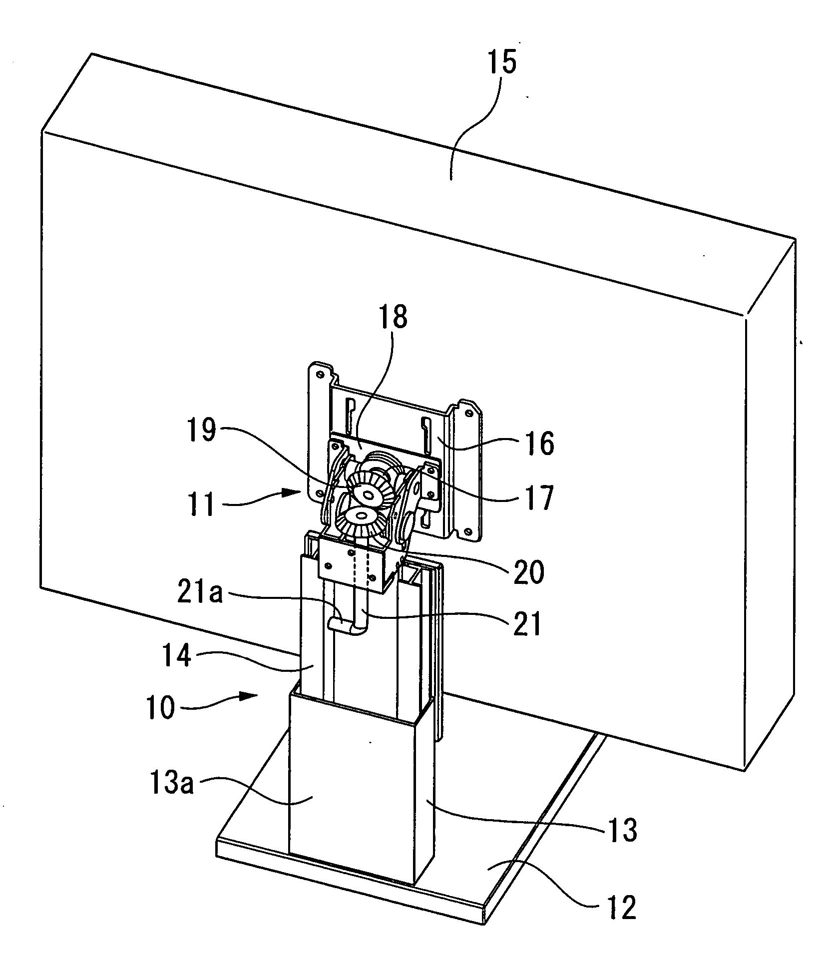
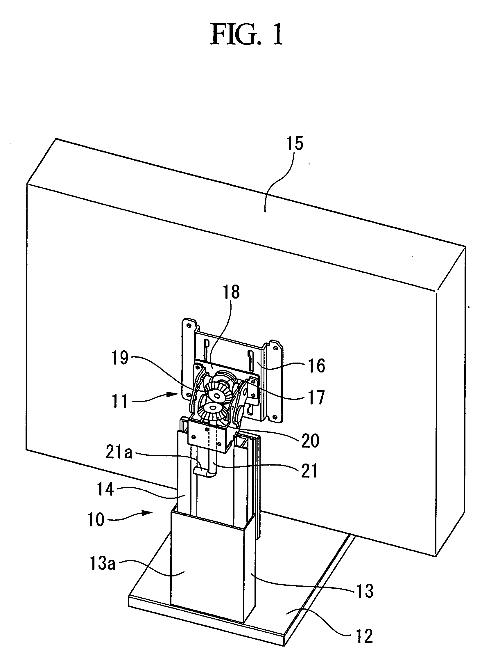
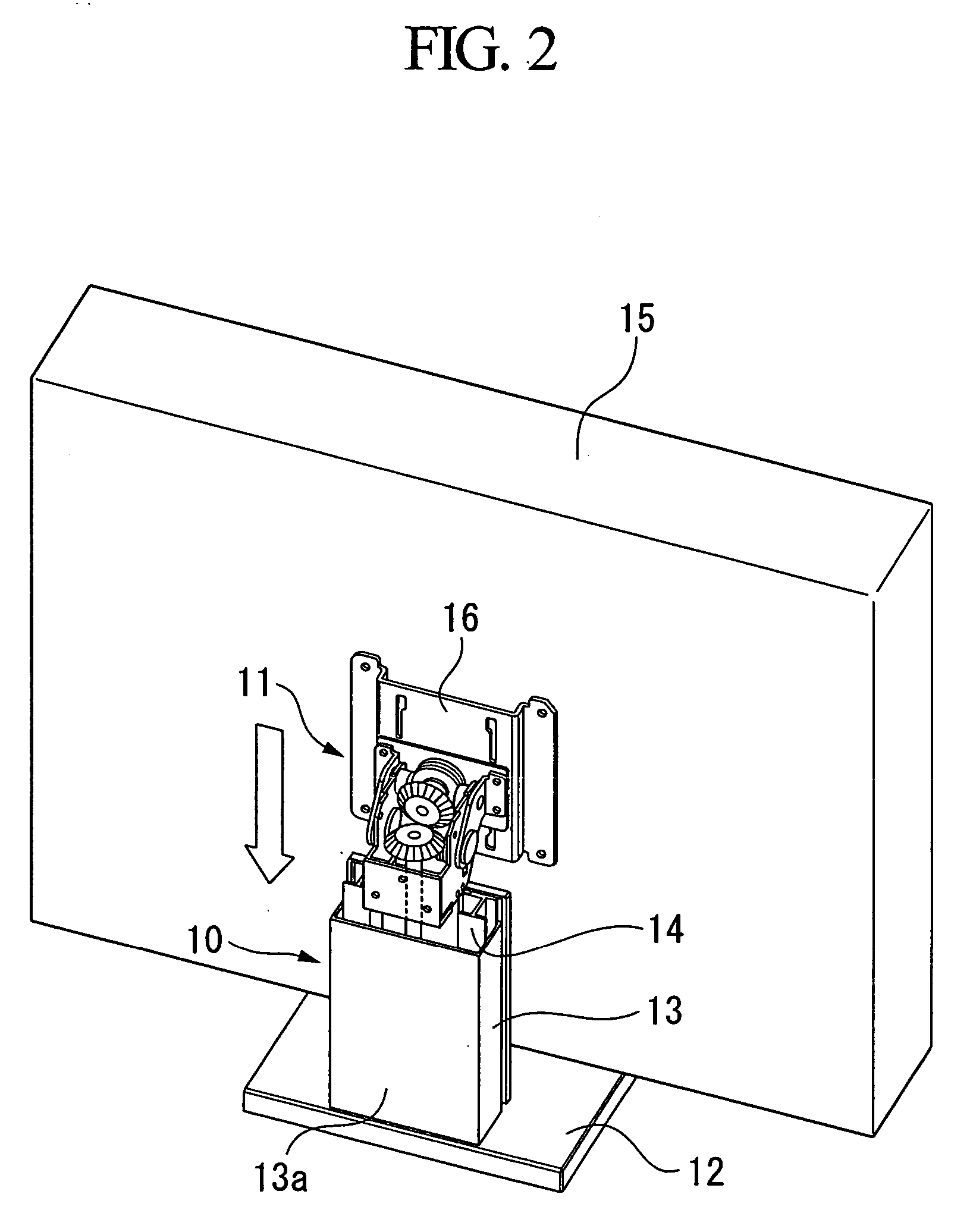
[0033] Referring to the figures, the invention will be described in detail. FIG. 1 is a perspective view of a stand for a thin display or a thin-display stand in a horizontal orientation of a first embodiment in accordance with the invention. FIG. 2 is a perspective view of the thin-display stand in a state when the thin-display stand is lowered at a lowest position. The thin-display stand includes a vertical position adjustment mechanism 10 and a changeover mechanism 11 for changing over between a vertical orientation in which a display screen 15 of the thin display is longer in a vertical direction and a horizontal orientation in which the display screen 15 is longer in a horizontal direction.
[0034] The vertical position adjustment mechanism 10 includes a support member 13 provided on a stand base 12 and a slide member 14 slidably mounted inside the support member 13. The slide member 14 can move up or down in a predetermined range. On the top of the slide member 14 is mounted the...
second embodiment
[0042]FIG. 5 is a perspective view of a thin-display stand of a second embodiment in accordance with the invention. In the embodiment, a switch over mechanism 50 includes the hold plate 18 for rotatably holding the mount axis 17 without restriction fixed on the mount plate 16 mounted on the back side of the display screen 15, a stopper arm 51 fixed on the tip of the mount axis 17, and a stopper projection 51 formed on the tip of the stopper arm 51.
[0043] As in the first embodiment, the mount plate 16 is in contact with the hold plate 18, which constitutes a contact plane. The display screen 15 is rotated by 90 degrees about the mount axis 17 in a plane parallel to the contact plane, which changes over between a vertical orientation and a horizontal orientation. The oval hole 22, which is concentric with the mount axis 17, is formed in a range of 90 degrees on the mount plate 16. A pin (not shown) that is inserted and moves in the oval hole 22 extrudes from the hold plate 18.
[0044] ...
third embodiment
[0047]FIG. 7 is a perspective view of a thin-display stand of a third embodiment in accordance with the invention. In the embodiment, a changeover mechanism 70 includes the hold plate 18 for rotatably holding the mount axis 17 without restriction fixed on the mount plate 16 mounted on the back side of the display screen 15 by a screw, a pinion gear 71 fixed on the tip of the mount axis 17, and a rack gear 72 engaging the pinion gear 71.
[0048] The pinion gear 71 rotates with the display screen 15. The rack gear 72 is slidably held by the slide member 14 of the vertical position adjustment mechanism 10. Consequently, with the rotation of the display screen 15, the rack gear 72 moves up or down along the slide member 14. As in the first embodiment, the hold plate 18 is always in contact with the mount plate, which forms a contact plane. The display screen 15 rotates by 90 degrees about the mount axis 17 in a plane parallel to the contact plane to change over between a vertical orientat...
PUM
 Abstract
Description
Claims
Application Information
 - R&D Engineer
- R&D Manager
- IP Professional
- Industry Leading Data Capabilities
- Powerful AI technology
- Patent DNA Extraction
Browse by: Latest US Patents, China's latest patents, Technical Efficacy Thesaurus, Application Domain, Technology Topic.
© 2024 PatSnap. All rights reserved.Legal|Privacy policy|Modern Slavery Act Transparency Statement|Sitemap