Protection for switched step up/step down regulators

a regulator and step-down technology, applied in the direction of dc-dc conversion, power conversion systems, instruments, etc., can solve the problems of abnormally high inductor current, abnormal current surge,

Active Publication Date: 2006-08-10
ANALOG DEVICES INT UNLTD
View PDF34 Cites 36 Cited by
  • Summary
  • Abstract
  • Description
  • Claims
  • Application Information

AI Technical Summary

Benefits of technology

[0024] An output feedback voltage is subtracted from a first voltage reference, the resultant voltage adjusted in accordance with clock frequency to obtain an adjusted resultant current. The adjusted resultant current is applied to charge a capacitor. The voltage at the capacitor is compared with a second reference voltage. If the capacitor voltage exceeds the second reference voltage, a signal is applied to effect connection of the inductor between the common potential and the output terminal. The capacitor is discharged when the inductor is not connected between the input and the output.
[0025] In yet another aspect, an on-time limitation protection is provided during buck mode control to avoid excessive inductor current during startup and low duty cycle operation. A voltage level related to the regulator duty cycle and switching frequency is sensed when the inductor is connected between input and output terminals. The voltage level is adjusted in accordance with clock frequency to obtain an adjusted resultant current. The adjusted resultant current is applied to charge a capacitor. The voltage at the capacitor is compared with a reference voltage. If the capacitor voltage exceeds the reference voltage, a signal is applied to effect connection of the inductor between the common potential and the output terminal for the remainder of the cycle. The capacitor is discharged when the inductor is not connected between the input and the output. The time during a clock cycle in which the inductor is connected to the input thus is limited.

Problems solved by technology

If a short circuit condition at the output were to occur, abnormal current surges can result.
Inductor current then increases without control to an abnormally high level.

Method used


Image

  • Protection for switched step up/step down regulators
  • Protection for switched step up/step down regulators
  • Protection for switched step up/step down regulators

Examples


Embodiment Construction

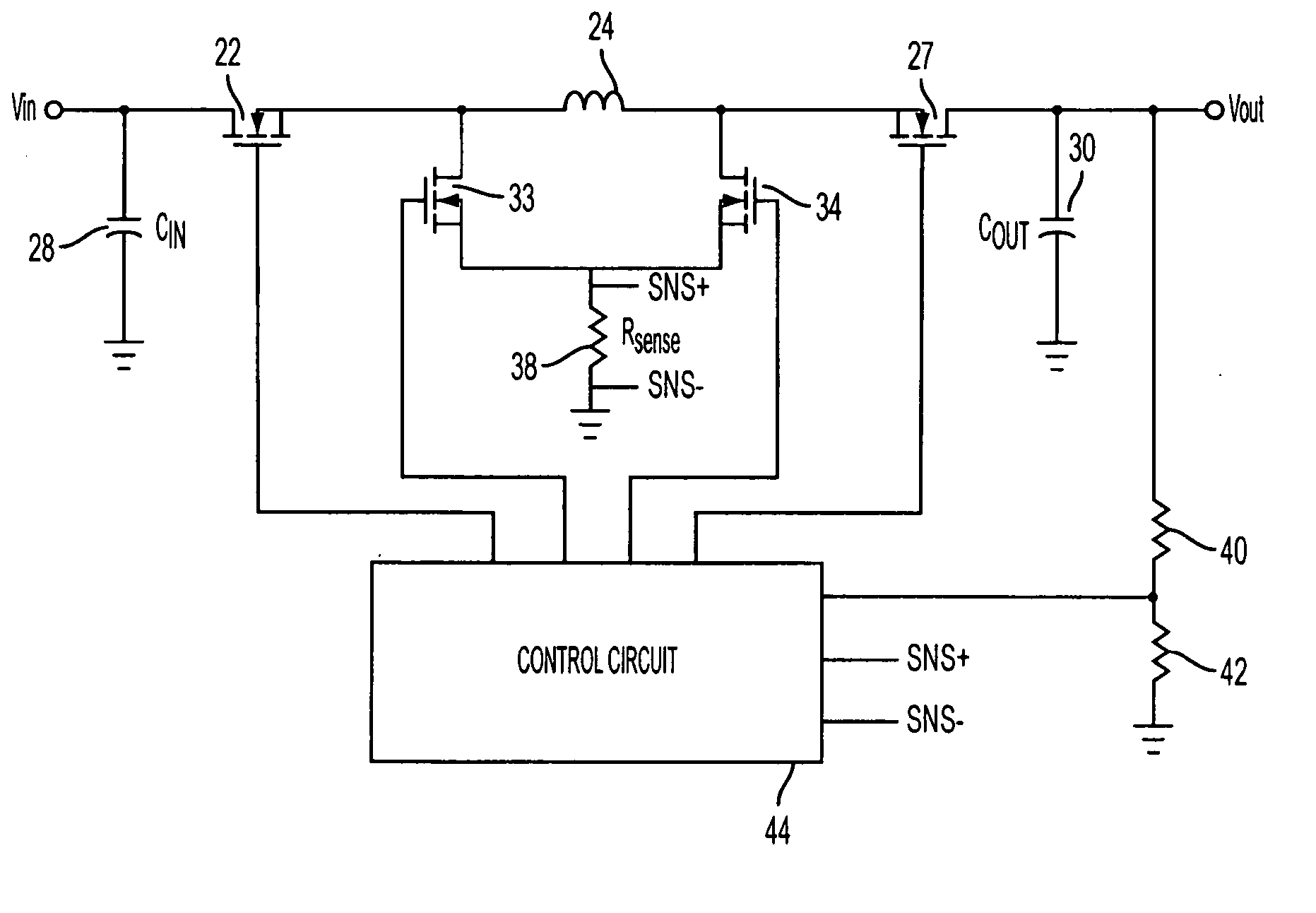
[0038]FIG. 6 is a block diagram of a protection circuit for the regulator of FIG. 1 during both buck mode and boost mode operations. Comparator 80 has a first input connected to receive voltage signal VC, the voltage across capacitor (C1) 82. A second input of comparator 80 receives reference voltage VREF2. The comparator generates an output signal V1. Connected across capacitor 82 is switch 84, represented schematically. Control circuit 44 generates a discharge signal, which is applied to switch 84 to discharge capacitor 82, when either of switch 22 is set to an open state.

[0039] Adder 86 has a first input that receives a reference voltage VREF1 and a second input that receives feedback voltage VFB. The feedback voltage may be taken, for example, from the junction of resistors 40 and 42 of FIG. 1. This voltage is fed to adder 86 with negative polarity so that the output of the adder represents the difference between VREF1 and VFB. This output is applied to one input of multiplier ...


PUM


Abstract

A four switch voltage converter is regulated for buck mode and boost mode under constant frequency valley-peak current mode control. Protection circuits are responsive to output voltage and regulator current to prevent excessive current that otherwise might result from abnormally low output voltage short circuit, or spurious switching abnormalities during low duty cycle operation. The regulator control circuit is responsive to the protection circuits to automatically connect a regulator inductor between a common potential and the output to limit current.

Description

RELATED APPLICATIONS [0001] This application contains subject matter related to copending U.S. application No. (Attorney docket no. 70386-029) of Flatness et al., filed ______, copending U.S. application No. (Attorney docket no. 70386-046) of Flatness et al., filed ______, and copending U.S. application No. (Attorney docket no. 70386-047) of Flatness et al., filed ______, all commonly assigned with the present application. The disclosures of these applications are incorporated by reference herein.TECHNICAL FIELD [0002] The present disclosure relates to control of regulators, more particularly to providing protection for switched regulators operating in buck and boost modes. Background [0003] Voltage regulators are known that can convert from input voltages above, below, or equal to controlled output voltages, respectively performing buck mode regulation, boost mode regulation, or buck-boost mode regulation. Regulator architecture typically is provided for power supplies for automoti...

Claims


Application Information

Patent Timeline
Patent Type & Authority Applications(United States)
IPC IPC(8): G05F1/40G05F1/618H02M1/00H02M1/32
CPCH02M1/32H02M3/1582
Inventor FLATNESS, RANDYZHOU, XUNWEI
Owner ANALOG DEVICES INT UNLTD
Why Eureka
Try Eureka