Augmented reality device and method

a technology of augmented reality and devices, applied in the field of augmented reality systems, can solve the problems of large errors in the user workspace, difficult calibration, and high display resolution, and achieve the effects of high display resolution, high display resolution, and high resolution

Inactive Publication Date: 2006-08-10
BLUE BELT TECH
View PDF51 Cites 636 Cited by
  • Summary
  • Abstract
  • Description
  • Claims
  • Application Information

AI Technical Summary

Benefits of technology

[0011] The present invention provides an augmented reality device to combine a real world view with information, such as images, of one or more objects. For example, a real world view of a patient's anatomy may be combined with an image of a bone within that area of the anatomy. The object information, which is created for example by ultrasound or a CAT scan, is presented on a display. An optical combiner combines the object information with a real world view of the object and conveys the combined image to a user. A tracking system tracks the location of one or more objects, such as surgical tools, ultrasound probe or body part to assure proper alignment of the real world view with object information. At least a part of the tracking system is at a fixed location with respect to the display. A non-head mounted eyepiece is provided at which the user can view the combined object and real world views. The eyepiece fixes the user location with respect to the display location and the optical combiner location so that the user's position need not be tracked directly.

Problems solved by technology

The necessity to track the user's viewpoint in this case is unnecessary because the device is mounted to the head, and the device's calibration process takes this into account.
Due to the closeness of the display to the eye, very small errors / motions in the position (or calculated position) of the display on the head translate to large errors in the user workspace, and difficulty in calibration.
High display resolutions are also much more difficult to realize for an HMD.
HMDs are also cumbersome to the user.
Calibration problems and a cumbersome nature also plague HMD video overlay systems.
This accomplishment actually limits the practical use of the system, in that the user has to peer through the mirror to the area where the image would be projected.
Mounting the mirror to allow this may result in a package that is not ergonomically feasible for the procedure for which it is being used.
Also, in order to display 3D images, SF would need to use a 3D display, which results in much higher technologic requirements, which are not currently practical.
Calibration and accuracy can be problematic in such configurations.
This technique involves the use of highly customized and expensive hardware, and is also very computationally expensive.
Devices tend to be very cumbersome for medical use and expensive, limiting there usefulness or affordability Accordingly, there is a need for an augmented reality system that can be easily calibrated, is accurate enough for surgical procedures and is easily used in a surgical setting.

Method used


Image

  • Augmented reality device and method
  • Augmented reality device and method
  • Augmented reality device and method

Examples


Embodiment Construction

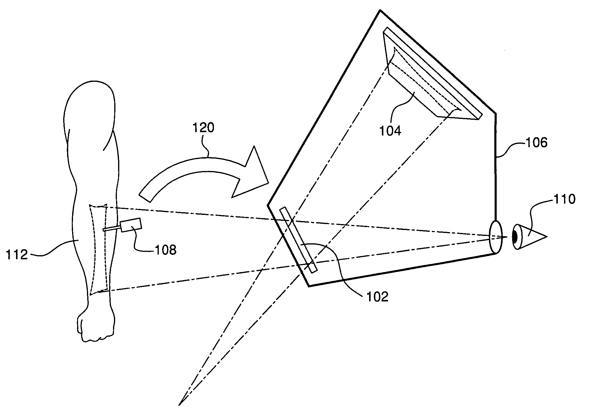
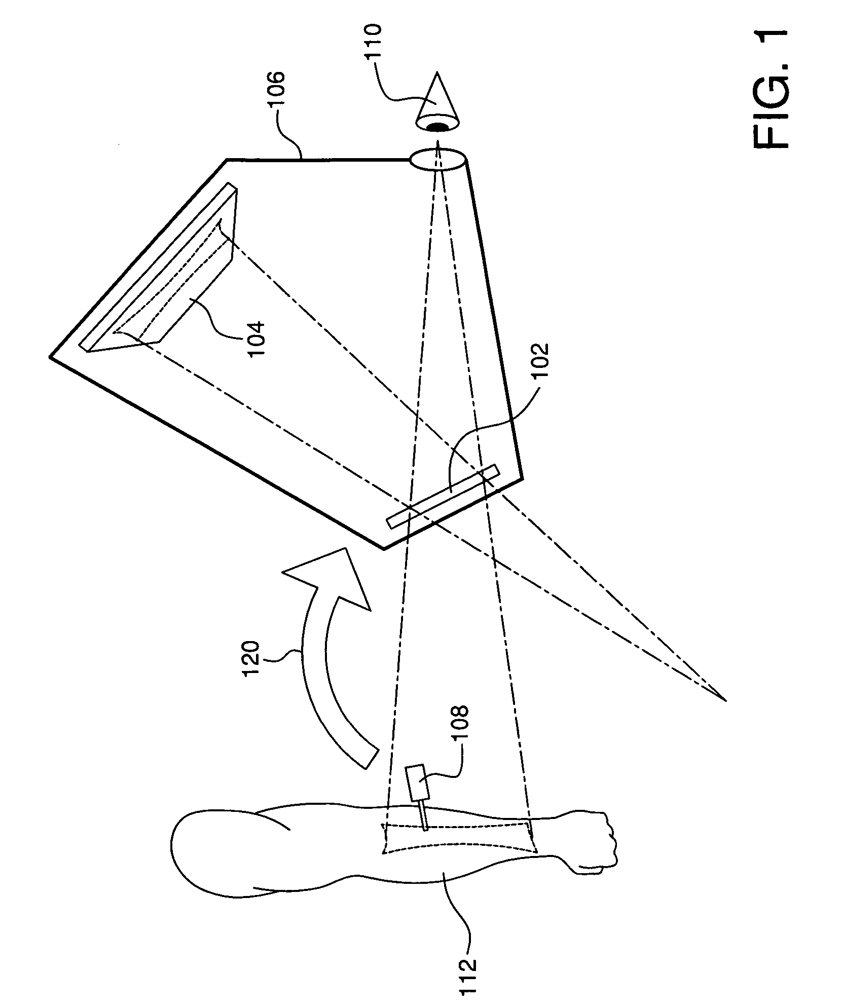
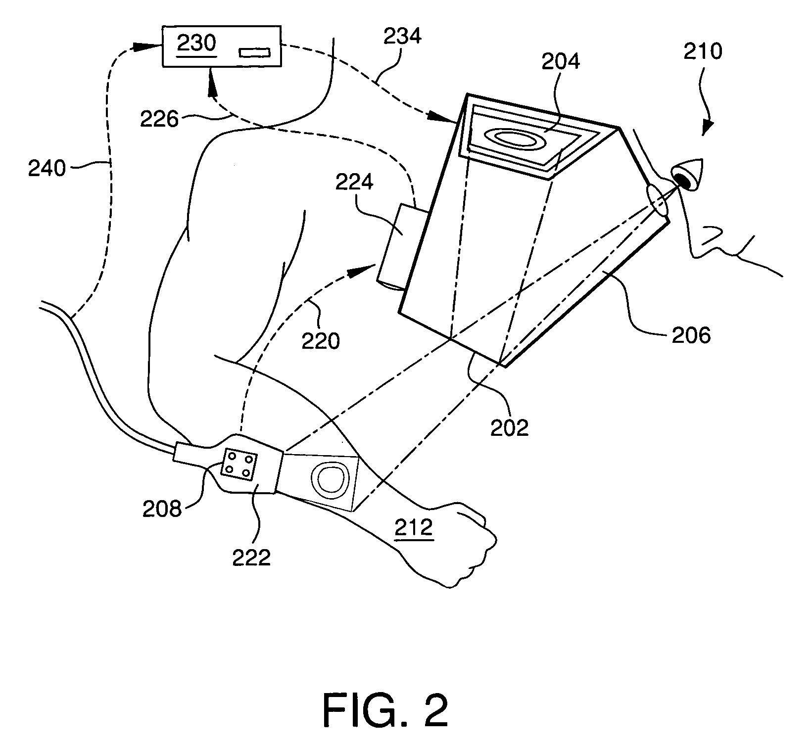
[0020] Advantageously, embodiments of the invention may provide an augmented reality device that is less sensitive to calibration and tracking accuracy errors, less cumbersome for medical use, less expensive and easier to incorporate tracking into the display package than conventional image overlay devices. An eyepiece is fixed to the device relative to the display so that the location of the projected display and the user's viewpoint are known to the system after calibration, and only the tools, such as surgical instruments, need to be tracked. The tool (and other object) positions are known through use of a tracking system. Unlike video-based augmented reality systems, which are commonly implemented in HMD systems, the actual view of the patient, rather than an augmented video view, is provided.

[0021] The present invention, unlike the SF has substantially unrestricted viewing positions relative to tools (provided the tracking system used does not require line-of-sight to the tool...


PUM


Abstract

An augmented reality device to combine a real world view with an object image. An optical combiner combines the object image with a real world view of the object and conveys the combined image to a user. A tracking system tracks one or more objects. At least a part of the tracking system is at a fixed location with respect to the display. An eyepiece is used to view the combined object and real world images, and fixes the user location with respect to the display and optical combiner location.

Description

[0001] This application is based on, and claims priority to, provisional application having Ser. No. 60 / 651,020, and a filing date of Feb. 8, 2005, entitled Image Overlay Device and MethodFIELD OF THE INVENTION [0002] The invention relates to augmented reality systems, and is particularly applicable to use in medical procedures. BACKGROUND OF THE INVENTION [0003] Augmented reality is a technique that superimposes a computer image over a viewer's direct view of the real world. The position of the viewer's head, objects in the real world environment, and components of the display system are tracked, and their positions are used to transform the image so that it appears to be an integral part of the real world environment. The technique has important applications in the medical field. For example, a three-dimensional image of a bone reconstructed from CT data, can be displayed to a surgeon superimposed on the patient at the exact location of the real bone, regardless of the position of...

Claims


Application Information

Patent Timeline
Patent Type & Authority Applications(United States)
IPC IPC(8): G09G5/00
CPCA61B5/0059A61B5/489A61B5/742A61B6/462A61B6/5247A61B8/00A61B8/4245A61B8/4254A61B8/461A61B8/462A61B8/5238A61B19/52A61B19/5244A61B2019/2249A61B2019/507A61B2019/5229A61B2019/5255A61B2019/5259A61B2019/5276A61B2019/5291A61B2019/5293G02B21/0012G02B21/36G02B27/01G02B27/017G02B2027/0134G02B2027/0138G02B2027/014G02B2027/0187G06F3/011A61B8/4263A61B8/466A61B34/20A61B34/72A61B90/36A61B2034/107A61B2034/2055A61B2034/2059A61B2090/365A61B2090/366A61B2090/372A61B2090/378
Inventor JARAMAZ, BRANISLAVNIKOU, CONSTANTINOSDIGIOIA, ANTHONY M. III
Owner BLUE BELT TECH
Why Eureka
Try Eureka