Motor and Recording Disk Driving Device

Active Publication Date: 2006-08-10
NIDEC CORP
View PDF16 Cites 6 Cited by
  • Summary
  • Abstract
  • Description
  • Claims
  • Application Information

AI Technical Summary

Benefits of technology

[0011] The exemplary electric motor according to the present invention enables reducing

Problems solved by technology

In order to reduce the thickness of a motor, if an attempt is made to reduce the base plate for mounting the stator and the like thereon, this will de

Method used


Image

  • Motor and Recording Disk Driving Device
  • Motor and Recording Disk Driving Device
  • Motor and Recording Disk Driving Device

Examples


first embodiment

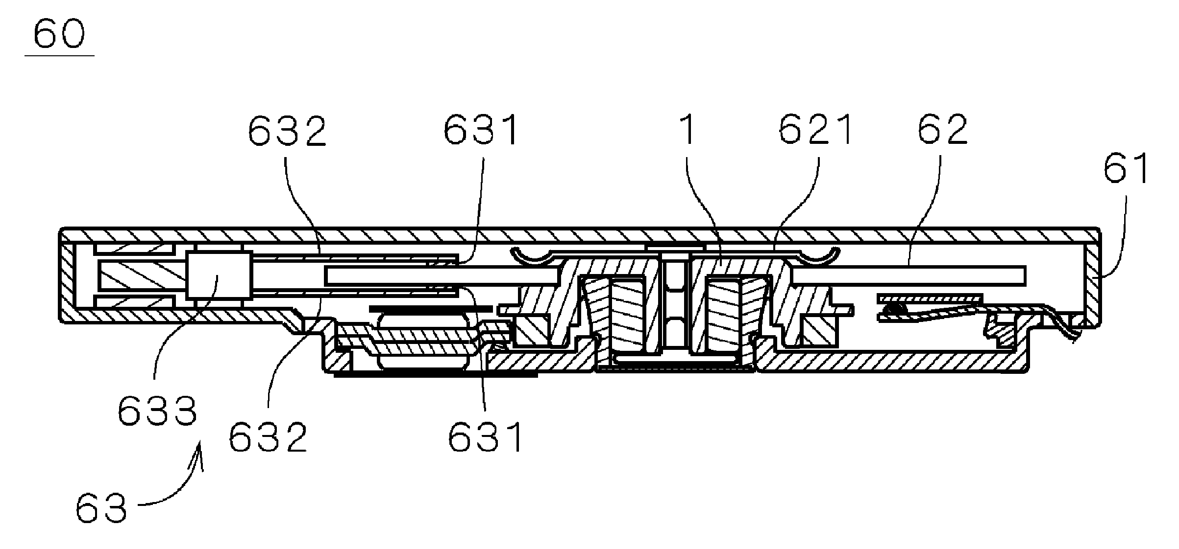
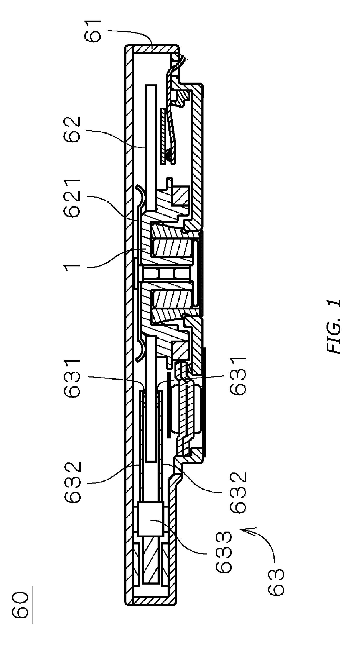
[0021]FIG. 1 is a view illustrating the internal structure of a disk driving device 60 including an electric spindle motor 1 (hereinafter, referred to as “a motor 1”) according to a first embodiment of the present invention. In the present embodiment, the disk driving device 60 is a hard-disk device. The disk driving device 60 includes a housing 61 having an internal space. The housing 61 houses a disk-shaped recording disk 62 for storing information, an accessing portion 63 for writing and / or reading information onto and / or from the recording disk 62, and the motor 1 for rotating the recording disk 62. The recording disk 62 is mounted on the upper side of the motor 1 and is secured to the motor 1 through a clamper 621.

[0022] The accessing portion 63 includes a head 631 provided near the recording disk 62 for magnetically writing and reading information thereonto and therefrom, an arm 632 for supporting the head 631, and a head moving mechanism 633 which moves the arm 632 for chang...

second embodiment

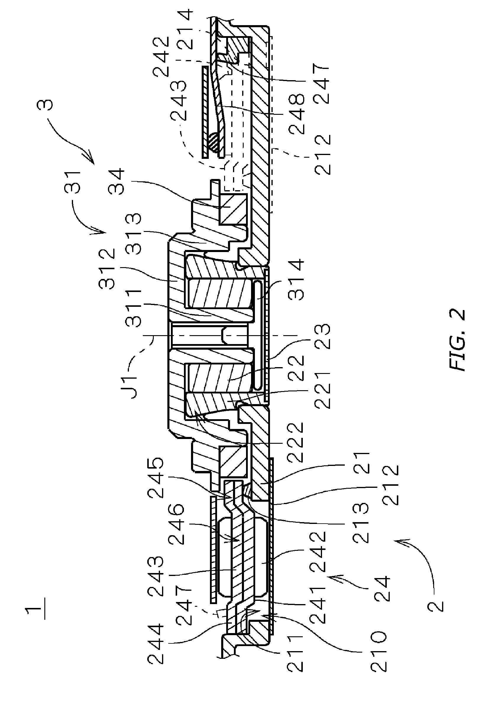
[0051] Next, there will be described a motor 1a according to a second embodiment of the present invention. FIG. 6 is a longitudinal cross-sectional view illustrating the structure of the motor 1a. As illustrated in FIG. 6, instead of the through holes 211 of the motor 1 illustrated in FIG. 2, a recessed portion 211a is formed on the base plate 21 in the motor 1a. The other structures are the same as those in FIG. 2 and will be designated by the same reference characters in the following description.

[0052] As illustrated in FIG. 6, the motor 1a includes a stationary section 2 and a rotor section 3, wherein the rotor section 3 is supported by a bearing mechanism utilizing fluid dynamic pressures of a lubricating oil such that it is rotatable about the center axis J1 with respect to the stationary section 2, similarly to in the first embodiment.

[0053] The bearing mechanism of the motor 1a also has the same structure as that in the first embodiment. The rotor section 3 includes a roto...


PUM


Abstract

A base plate is provided with plural through holes extending vertically through the base plate, at the portions aligned with plural teeth. In the respective through holes of the base plate, the lower portions of wire-wound portions of the corresponding teeth and the lower portions of the coils formed around the wire-wound portions are inserted. The lower surfaces of the wire-wound portions are positioned between the upper main surface and the lower main surface of the base plate in the axial direction.

Description

BACKGROUND OF THE INVENTION [0001] 1. Field of the Invention [0002] The present invention relates to electric motors and recording disk driving devices including a motor. [0003] 2. Background Art [0004] Conventionally, recording-disk driving devices such as hard-disk devices include a spindle motor (hereinafter, referred to as “a motor”) for rotating and driving a recording disk. In recent years, recording-disk driving devices have been mounted on portable music players, etc., and, therefore, there has been a need for recording disk driving devices with large capacities, reduced sizes and reduced thicknesses. Accordingly, there has been a need for motors with reduced sizes and thicknesses as the driving power sources of such recording disk driving devices. [0005] In order to reduce the thickness of a motor, if an attempt is made to reduce the base plate for mounting the stator and the like thereon, this will degrade the rigidity of the base plate, thus resulting in the occurrences o...

Claims


Application Information

Patent Timeline
IPC IPC(8): G11B17/02
CPCG11B25/043H02K1/146H02K1/185H02K3/18H02K21/14
Inventor TAMAOKA, TAKEHITO
Owner NIDEC CORP
Why Eureka
Try Eureka