Test head positioning system

a positioning system and test head technology, applied in the direction of stacking articles, instruments, manufacturing tools, etc., can solve the problems of limited vertical stroke provided by the manipulator high cost of the test head, and inability to meet the needs of the user

Active Publication Date: 2006-08-10
INTEST CORP
View PDF16 Cites 33 Cited by
  • Summary
  • Abstract
  • Description
  • Claims
  • Application Information

AI Technical Summary

Benefits of technology

[0022] According to yet another exemplary embodiment of the present invention, a method of manipulating a load is provided. The method includes at least partially supporting the load in a compliant state in a direction or about an axis by pressurizing a fluid, such that the load may be moved in the direction or about the axis using a first manual amount of force. The method also includes remotely adjusting the fluid pressure such that the load may be moved in the direction or about the axis using a second manual amount of force until an operator can manipulate the load in the direction or about the axis. The second manual amount of force is less than the first manual amount of force.

Problems solved by technology

Because test heads are typically very expensive, it is often desirable to use the same test head to dock with various different peripherals.
However, because of size constraints on test heads and the associated manipulators, this is not always practical.
In such a design, the vertical stroke provided by the test head manipulator is limited by the stroke of the pneumatic cylinder arrangement.
Often, with larger test heads, the stroke of a pneumatic cylinder arrangement is inadequate to provide a vertical range of motion adequate for docking a test head with the different types of peripherals.
Another problem that arises when trying to dock a test head with different types of peripherals is that during manipulation of the test head, a degree of freedom may be lost.
Conventional attempts at alleviating such a lost degree of freedom have resulted in increasingly complex and expensive manipulator systems.
However, as test heads have become larger and heavier, the physical force required to manually manipulate the test head in certain directions (even in a compliant state) may be difficult if not impossible for certain operators to provide.

Method used


Image

  • Test head positioning system
  • Test head positioning system
  • Test head positioning system

Examples


Embodiment Construction

[0060] Preferred features of selected embodiments of this invention will now be described with reference to the figures. It will be appreciated that the spirit and scope of the invention is not limited to the embodiments selected for illustration. Also, it should be noted that the drawings are not rendered to any particular scale or proportion. It is contemplated that any of the configurations and materials described hereafter can be modified within the scope of this invention.

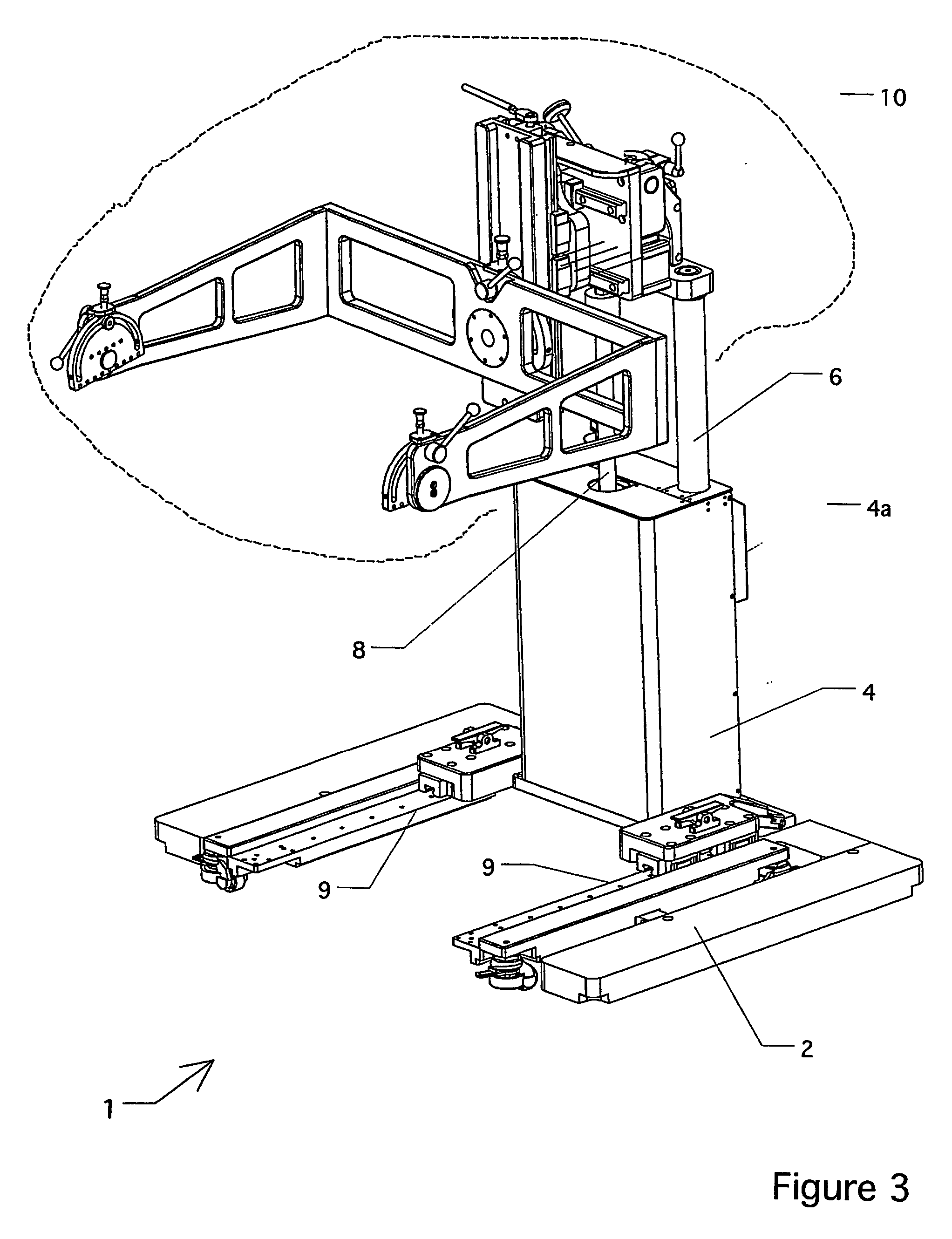
[0061]FIG. 3 is a perspective view of test head manipulator 1. Test head manipulator 1 includes base 2, vertical column unit 4, control enclosure 4a, test head attachment unit 10, guide rails 6 (only one guide rail 6 is visible in FIG. 3) that extend between column unit 4 and test head attachment unit 10, and piston rod 8 also extending between column unit 4 and test head attachment unit 10. Piston rod 8 extends from a “main vertical pneumatic cylinder” contained within column unit 4, and it provides a vertic...


PUM


Abstract

An apparatus (1) for manipulating a load includes a first support structure (60) for supporting the load and a second support structure (4) for supporting the load. The apparatus also includes a coupling (3) coupled between the first support structure (60) and the second support structure (4). The coupling (30) includes a compliant mechanism (340a) for providing a compliant range of motion to the load about a rotative axis where a center of gravity of the load is located away from the rotative axis. The rotative axis is a non-vertical axis.

Description

FIELD OF THE INVENTION [0001] The present invention relates to systems for positioning and manipulating loads, and more particularly, to systems for positioning and manipulating test heads. BACKGROUND OF THE INVENTION [0002] Test heads are often utilized in the testing of integrated circuits. In order to use a test head to test integrated circuits, the test head is typically “docked” to a piece of peripheral equipment such as a prober or a device handler (hereinafter “peripheral”). A test head manipulator is typically used to position and manipulate the test head during the docking operation. [0003] In docking a test head to a peripheral, it is desirable that the test head be moveable in a number of directions (i.e., that the test head have a number of degrees of freedom). Further, it is, also desirable to have the test head be compliantly moveable with respect to various degrees of freedom (i.e., the test head is substantially weightless or may be moved with a relatively small amou...

Claims


Application Information

Patent Timeline
Patent Type & Authority Applications(United States)
IPC IPC(8): B65G57/00B25J9/10G01R1/073G01R31/28
CPCG01R31/2891G01R31/2887G01R1/073
Inventor MUELLER, CHRISTIAN
Owner INTEST CORP
Why Eureka
Try Eureka