
Flash memory control devices that support multiple memory mapping schemes and methods of operating same

a control device and flash memory technology, applied in the field of data storage devices, can solve the problems of disk storage damage, large memory capacity at a low price, and require delicate mechanical techniques

Active Publication Date: 2006-08-10
SAMSUNG ELECTRONICS CO LTD
View PDF13 Cites 92 Cited by
  • Summary
  • Abstract
  • Description
  • Claims
  • Application Information

AI Technical Summary

Benefits of technology

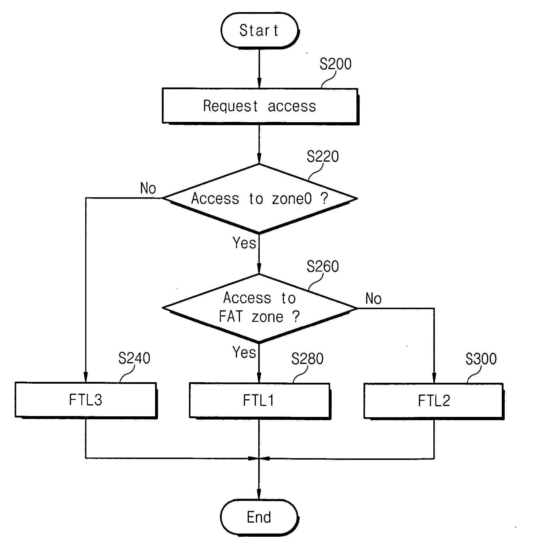
[0017] Embodiments of the invention include an apparatus for controlling a flash memory. This apparatus includes a memory for storing a plurality of flash translation layers and a control block for, when an external access is requested, determining a pattern of the access, selecting one of the flash translation layers stored in the memory based on the determination result, and managing mapping data of the flash memory based on the selected flash translation layer. The control block (unit) may extract logical address information from data inputted when the access is requested and determine the pattern of access based on the extracted logical address information. In addition, the control block may accumulate the access pattern information whenever an access is r

Problems solved by technology

Generally, disk storage provides a large memory capacity at a low price, but may require delicate mechanical techniques to perform various operations, (e.g., disk searching), with a magnetic head.
Thus, the disk storage may be damaged by physical impact, which makes it less reliable than other kinds of memory devices.
One drawback to using a flash memory device includes the requirement that an erasure operation should be performed before a program operation.
Another drawback includes the requirement of using high voltages (e.g., 12V or 20V) to perform erasure operations.
The FTL connects a flash memory card to a file system used in a particular operating system and it does not allow writing more than once to the same address without prior erasure.
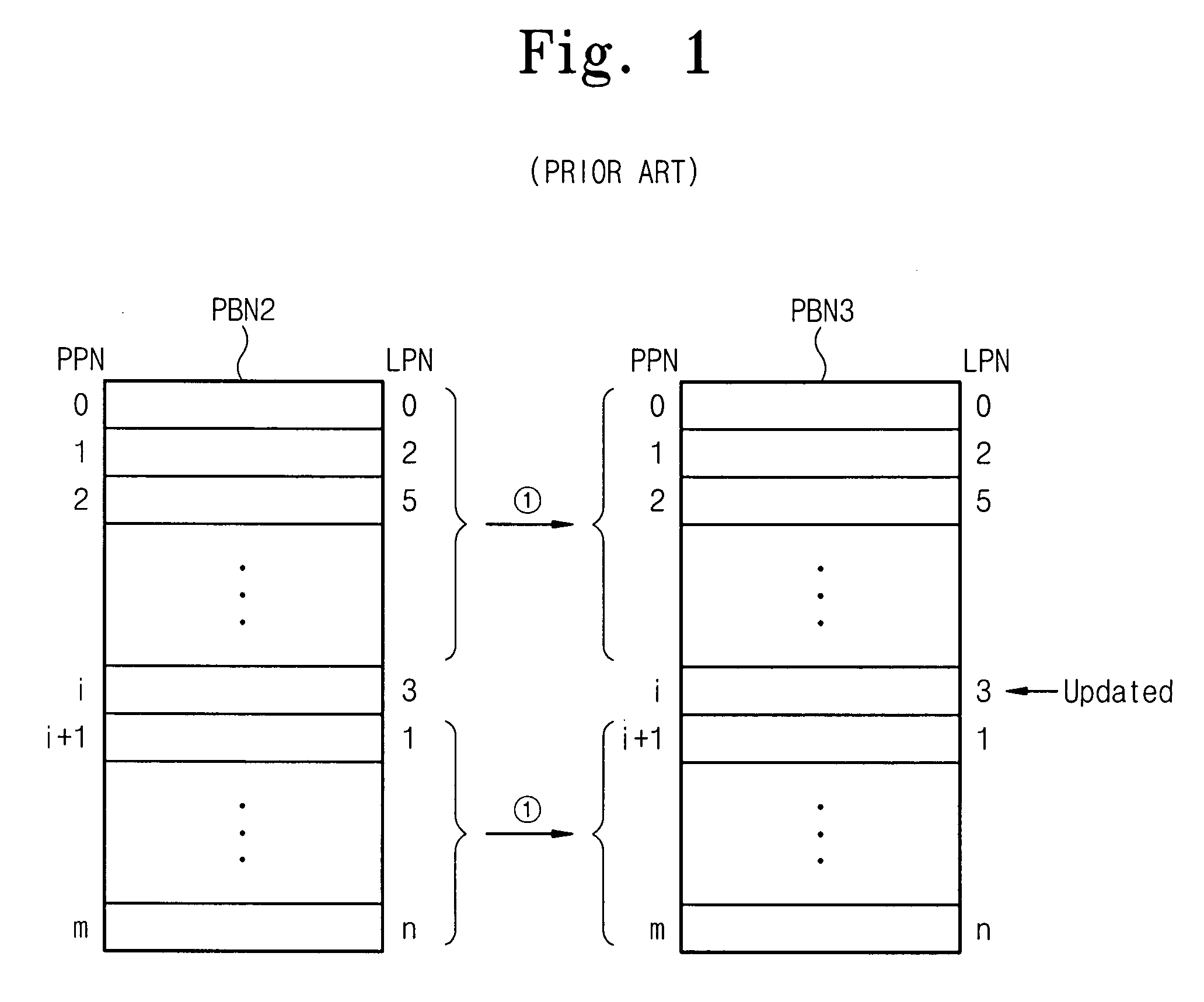
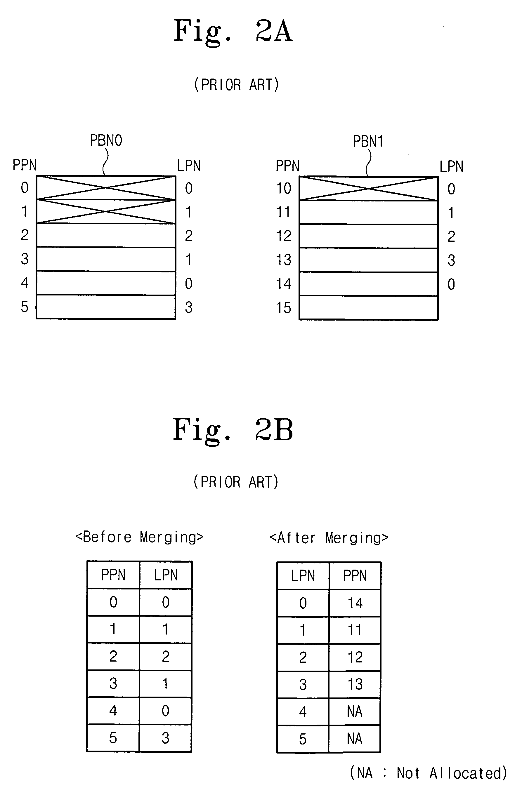
The log mapping scheme has a disadvantage in that the merging should be carried out whenever a small quantity of data is written into different data blocks, while it has an advantage in that it can write a large quantity of data easily.
However, since different access patterns are processed by only a single FTL, the performance of the entire system can be degraded.

Method used


Image

  • Flash memory control devices that support multiple memory mapping schemes and methods of operating same
  • Flash memory control devices that support multiple memory mapping schemes and methods of operating same
  • Flash memory control devices that support multiple memory mapping schemes and methods of operating same

Examples


Embodiment Construction

[0030] The present invention now will be described more fully herein with reference to the accompanying drawings, in which preferred embodiments of the invention are shown. This invention may, however, be embodied in many different forms and should not be construed as being limited to the embodiments set forth herein; rather, these embodiments are provided so that this disclosure will be thorough and complete, and will fully convey the scope of the invention to those skilled in the art. Like reference numerals refer to like elements throughout and signal lines and signals thereon may be referred to by the same reference characters. Signals may also be synchronized and / or undergo minor boolean operations (e.g., inversion) without being considered different signals.

[0031]FIG. 4 is a block diagram illustrating a flash memory system 1000 in accordance with an embodiment of the present invention. Referring to FIG. 4, the flash memory system 1000 according to the present embodiment inclu...


PUM


Abstract

There is provided an apparatus for controlling a flash memory, which includes a memory for storing a plurality of flash translation layers; and a control block for, when an access is requested from outside, determining a pattern of the access, selecting one of the flash translation layers stored in the memory based on the determination result, and managing mapping data of the flash memory based on the selected flash translation layer.

Description

REFERENCE TO PRIORITY APPLICATION [0001] This application claims priority to Korean Patent Application No. 10-2005-0011300, filed Feb. 7, 2005, the disclosure of which is hereby incorporated herein by reference. FIELD OF THE INVENTION [0002] The present invention relates to data storage devices and, more particularly, to flash memory devices and methods of operating flash memory devices. BACKGROUND OF THE INVENTION [0003] Diverse forms of personal computers, such as desktop computers for office and laptop computers for a mobile environment have been developed for commercial and personal use. A computer system may include a main memory and an external storage device. The external storage device may have a large memory capacity and a low unit price. External storage devices include a conventional hard disk drive (HDD) and a floppy disk drive (FDD) used in a disk storing medium. Generally, disk storage provides a large memory capacity at a low price, but may require delicate mechanical...

Claims


Application Information

Patent Timeline
IPC IPC(8): G06F12/00
CPCG06F12/0246G06F2212/7201G06F2212/7205A63C17/016A63C17/0046A63C17/004A63C17/10A63C2203/20
Inventor KIM, JIN-HYUKCHOI, YOUNG-JOONPARK, CHAN-IK
Owner SAMSUNG ELECTRONICS CO LTD
Learn More