
Reliable standby database failover

a standby database and failover technology, applied in the field of database processing, can solve the problems of primary database failure, standby database cannot recover redo transaction data, archived primary redo log file cannot be applied,

Inactive Publication Date: 2006-08-10
ORACLE INT CORP
View PDF9 Cites 29 Cited by
  • Summary
  • Abstract
  • Description
  • Claims
  • Application Information

AI Technical Summary

Benefits of technology

This approach guarantees data integrity and simplifies the failover process by ensuring consistent data across databases, reducing the need for manual intervention and minimizing errors, thus facilitating quicker and more reliable database recovery.

Problems solved by technology

However, the archived primary redo log file can't be applied until the primary log file switch occurs.
An apparent failure of the primary database may be caused by hardware problems, software problems, or loss of communications with the primary database site.
In the event of failure of the primary database, the standby database will not be able to recover any redo transaction data contained in the primary database's redo log files as the primary database and associated log files are most likely unavailable due to the failure.
The standby database is guaranteed to have a data loss, which could potentially be very large if the primary database's online logs were large and nearly full.
A manual recovery of a standby database is very manual-intensive and highly prone to incorporate human caused errors.
However, it is impossible to guarantee that transmission occurred for all elements of a transaction, i.e. atomically, for both the primary and standby redo log files.
However, a multiple log file update can cause serious database data integrity problems, as transactions may be applied multiple times. A transaction can often affect a number of database records and fields.
This manual recovery of a database is requires a large number of man hours, is very time consuming, and is highly prone to the creation of additional errors in the database and the log files, and therefore is to be avoided.
However, once the problem, such as with data integrity, has been determined, a great deal of time and manual effort is required to fix the database.
Existing systems cannot guarantee that data integrity will be preserved in all fail-over and recovery scenarios.

Method used


Image

  • Reliable standby database failover
  • Reliable standby database failover
  • Reliable standby database failover

Examples


Embodiment Construction

(s)

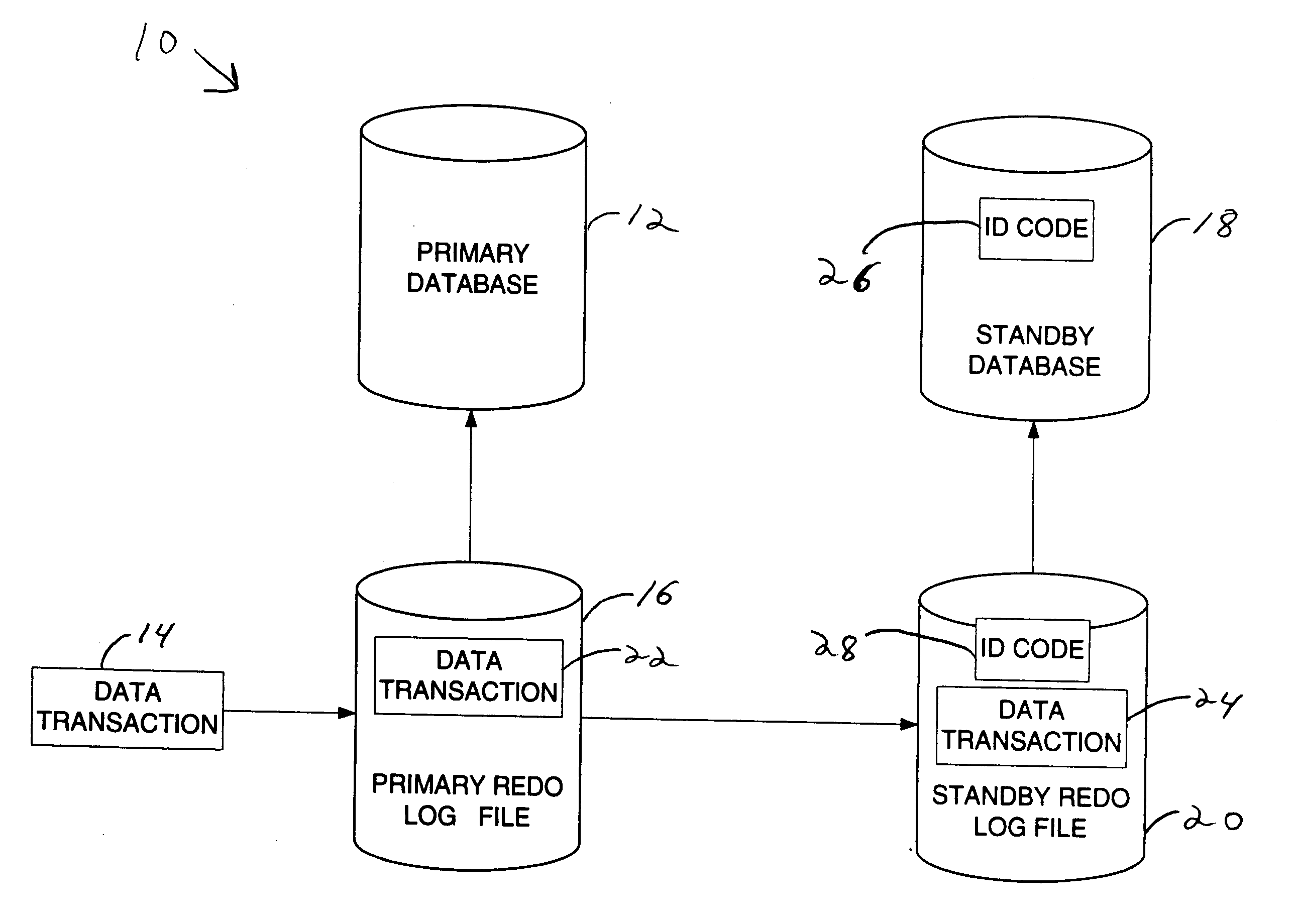
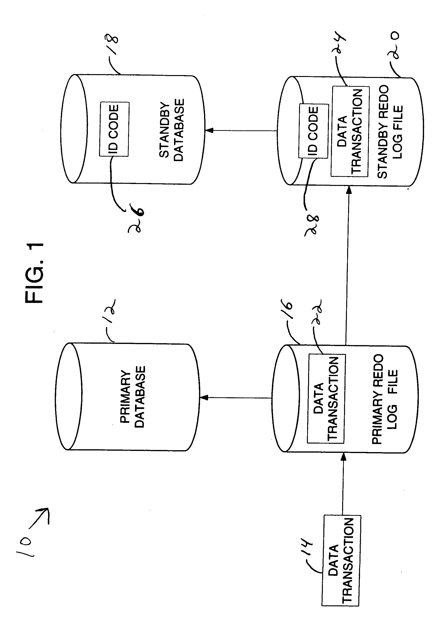
[0028] Referring to FIG. 1, a block diagram view of a system 10 incorporating features of the present invention is illustrated. Although the present invention will be described with reference to the embodiments shown in the drawings, it should be understood that the present invention can be embodied in many alternate forms of embodiments. In addition, any suitable size, shape or type of elements or materials could be used.

[0029] The present invention generally provides terminal recovery of a database during a failover. For the purpose of explanation, embodiments of the invention shall be described in the context of a database system having at least one standby database and redo logs. The present invention is not limited to any particular type of database system, or any particular form of data containers for the base or summary data.

[0030] As shown in FIG. 1, the database system 10 generally comprises a primary database 12 for receiving data transactions 14. Associated with the ...


PUM


Abstract

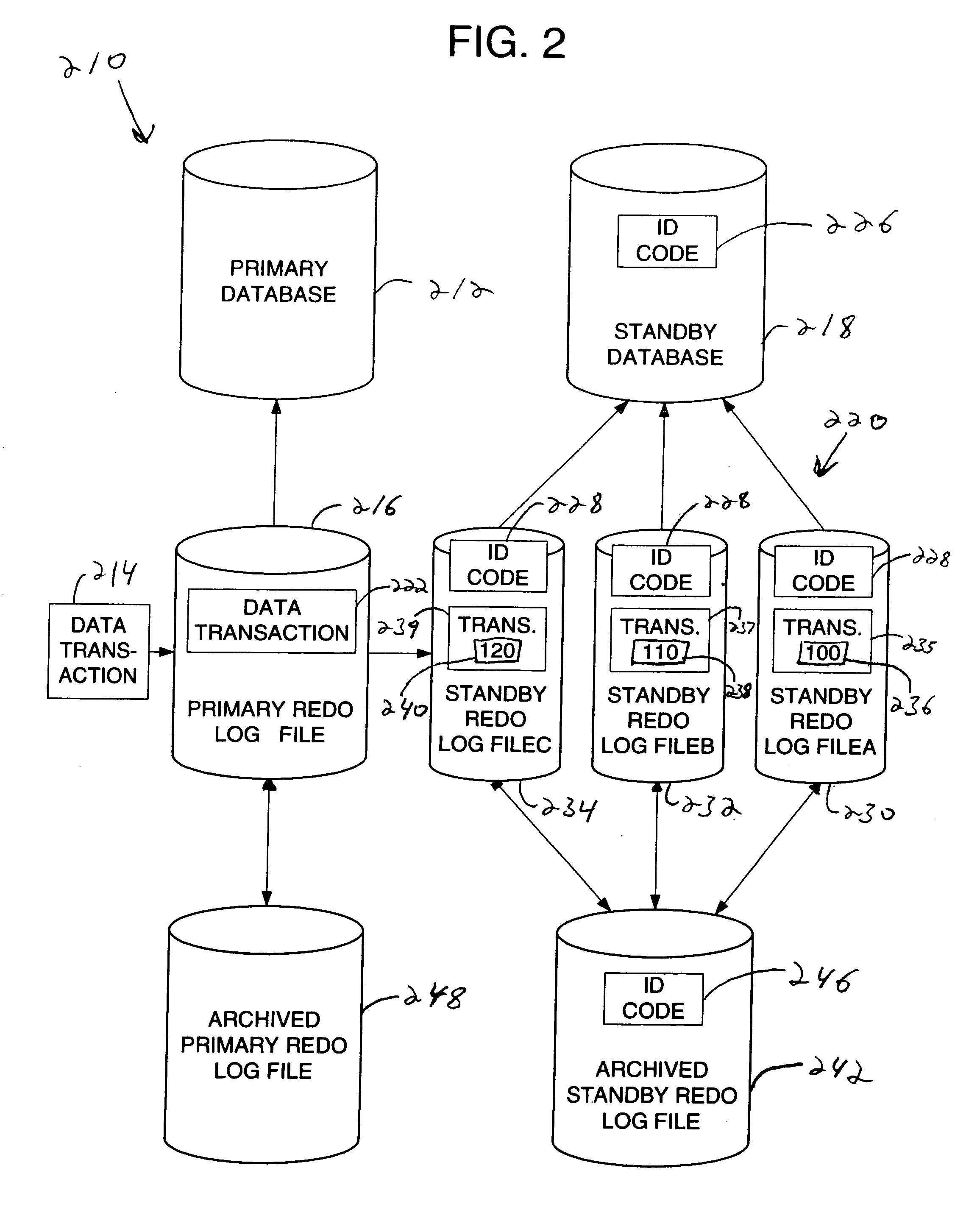
A method for providing data integrity of a database system. A standby database is selected to replace a failed primary database. At least one redo log file having at least one data transaction is selected to be applied to the selected standby database. The selected standby database is updated with the data transaction from the selected redo log file if an identification code in the redo log file matches an identification code in the standby database.

Description

BACKGROUND OF THE INVENTION [0001] 1. Field of the Invention [0002] The present invention relates to database processing and, more particularly, to providing data integrity during a database failover. [0003] 2. Brief Description of Related Developments [0004] Database systems often include a primary database and backup, or standby, databases. The standby databases can be located locally or remotely relative to the primary database. Log files are associated with each of the primary and standby databases to preserve the integrity of the data in the database system. Generally, log files are used to record data transactions applied to the primary database, so that if the primary database is damaged in some way, the log files can be used to restore the damaged or missing data to the standby database. [0005] In a database system configuration containing the primary database and the standby database, and the standby database is recovered by applying archived redo log files from the primary...

Claims


Application Information

Patent Timeline
Patent Type & Authority Applications(United States)
IPC IPC(8): G06F11/00
CPCG06F11/2023G06F11/2097Y10S707/99953
Inventor ANDERSON, RICHARD JAMES JR.BENTON, BARBARA A.BRIDGE, WILLIAM HAVINDEN JR.
Owner ORACLE INT CORP
Learn More