Determining the extent of a lateral shadow zone in an ultrasound inspection method

a technology of lateral shadow zone and ultrasound inspection method, which is applied in the direction of vibration measurement in solids, instruments, static/dynamic balance measurement, etc., to achieve the effect of convenient implementation

Active Publication Date: 2006-08-17
SN DETUDE & DE CONSTR DE MOTEURS DAVIATION S N E C M A
View PDF4 Cites 3 Cited by
  • Summary
  • Abstract
  • Description
  • Claims
  • Application Information

AI Technical Summary

Benefits of technology

[0009] A particular object of the invention is to determine a lateral shadow zone of a part in an ultrasound inspection method, where such determination is accurate, reliable, and easy to implement.

Problems solved by technology

The known technique does not make it possible to determine the exact extent of said dead zone at arbitrary depth in the part, and it is therefore necessary as a precaution to give it a maximum value, e.g. 12 millimeters (mm) even though it might be much smaller in reality, e.g. half that, which corresponds to ignoring a relatively large amount of matter.

Method used


Image

  • Determining the extent of a lateral shadow zone in an ultrasound inspection method
  • Determining the extent of a lateral shadow zone in an ultrasound inspection method
  • Determining the extent of a lateral shadow zone in an ultrasound inspection method

Examples


Embodiment Construction

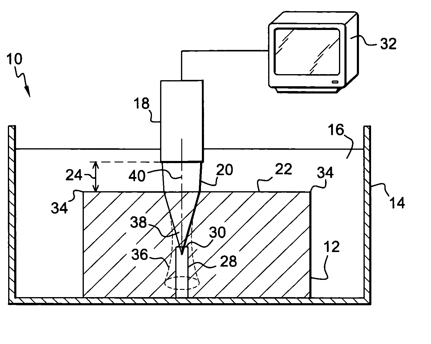
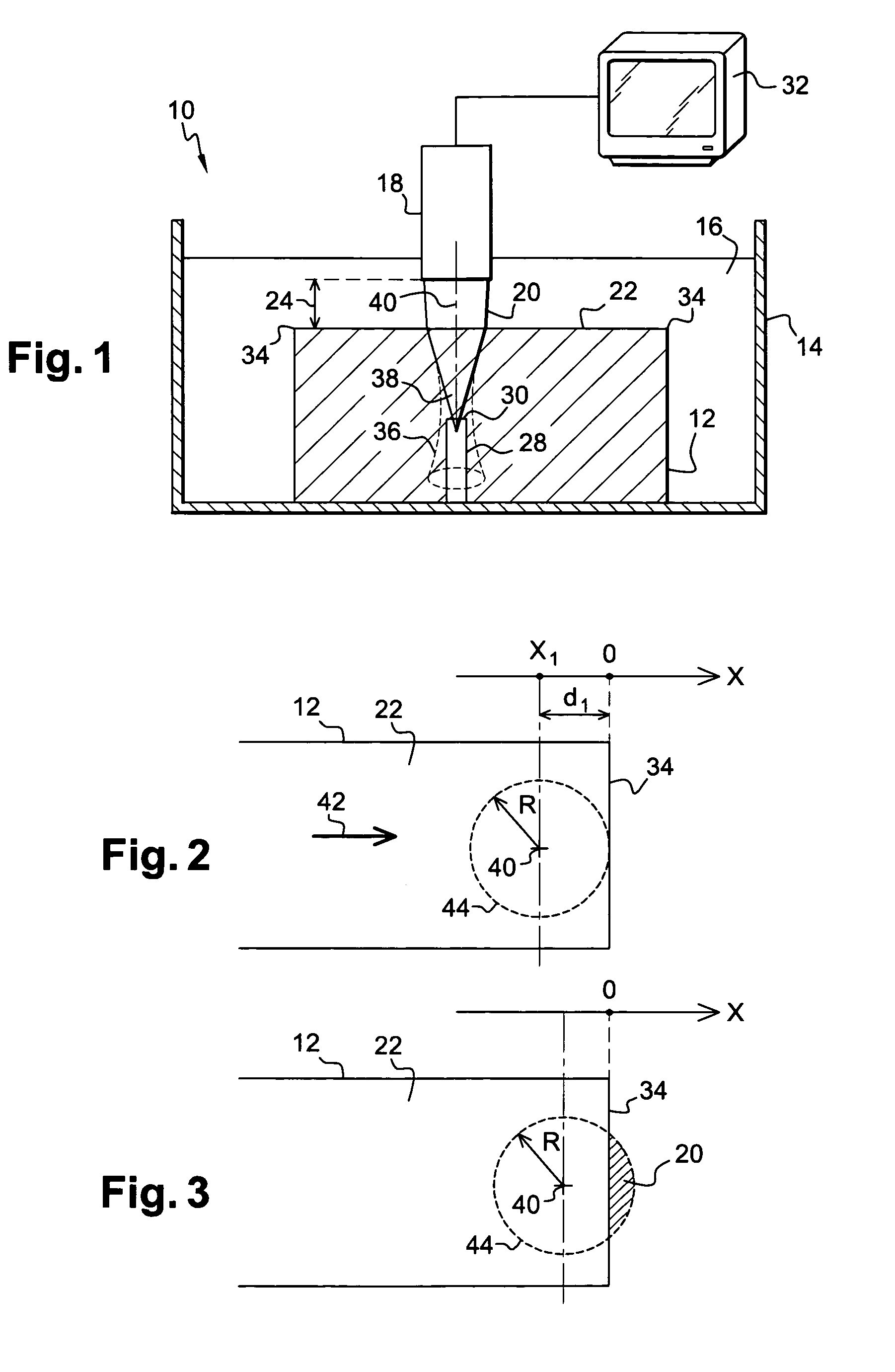
[0029]FIG. 1 is a diagram showing a device 10 for inspecting a part 12 in immersion by means of an ultrasound beam, the device comprising a vessel 14 filled with water 16 in which the part 12 for inspection and an electroacoustic transducer 18 are both immersed, the transducer serving to generate an ultrasound beam 20 oriented perpendicularly to a surface 22 of the part 12, the transducer 18 being spaced apart from said surface 22 by a depth of water referred to as the “water column”24.

[0030] The transducer 18 is connected to control means (not shown), such as a microcomputer, and to pulse generator means.

[0031] Some of the emitted ultrasound waves is reflected at the surface 22 of the part and the remainder are transmitted into the inside of the part, with the ultrasound waves propagating within the part 12 possibly encountering on their trajectory a defect that is capable of reflecting them. A defect might be constituted, for example, by a bubble, an inclusion, etc., and one suc...


PUM


Abstract

A method of determining the extent of a lateral shadow zone corresponding to an edge of a part in a method of inspecting the part in immersion by means of an ultrasound beam, the method consisting in determining the extent of the shadow zone from the edge of the part by measuring the effective section of the ultrasound beam at the surface of the part, and in determining said effective section from variations in the amplitude of an echo of the beam as a function of the distance between the axis of the beam and the edge of the part.

Description

[0001] The present invention relates to determining the extent of a lateral shadow zone corresponding to an edge of a part, in a method of using an ultrasound beam to inspect the part while it is immersed. BACKGROUND OF THE INVENTION [0002] Inspecting a part in immersion by means of an ultrasound beam serves to detect defects in the part such as, for example: bubbles, inclusions, etc. [0003] The technique is implemented in a vessel filled with an acoustic coupling liquid, such as water, having an ultrasound generator, such as an electroacoustic transducer, that is immersed in the water and that is oriented towards the part for inspection perpendicularly to a surface thereof, the transducer being spaced apart from said surface of the part by a depth of water referred to as the “water column”. [0004] The transducer emits a beam of ultrasound waves which is partially reflected on the surface of the part and partially transmitted to the inside of the part, the transmitted ultrasound wav...

Claims


Application Information

Patent Timeline
Patent Type & Authority Applications(United States)
IPC IPC(8): G01H13/00
CPCG01N29/06G01N29/11G01N29/265G01N29/28G01N2291/02854G01N2291/2632
Inventor CHATELLIER, JEAN-YVESCOULETTE, RICHARD
Owner SN DETUDE & DE CONSTR DE MOTEURS DAVIATION S N E C M A
Why Eureka
Try Eureka