Impact tool

Active Publication Date: 2006-08-17
MAKITA CORP
View PDF10 Cites 56 Cited by
  • Summary
  • Abstract
  • Description
  • Claims
  • Application Information

AI Technical Summary

Benefits of technology

[0027] With this configuration, the contact state between the firs

Problems solved by technology

Therefore, the number of parts will be naturally increased, and the assembling work well be troublesome.
Further, there is a probability that the parts are fallen out when the impact driver is disassembled for the maintenance purpose.
Since the internal gear

Method used


Image

  • Impact tool
  • Impact tool
  • Impact tool

Examples


Embodiment Construction

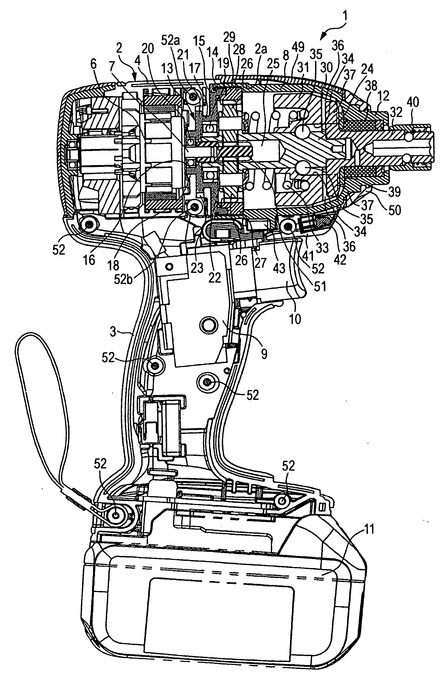
[0033] As shown in FIG. 1, an impact driver 1 according to one embodiment of the invention is roughly constituted by right and left half housings 4, 5 (see also FIG. 4) and a housing body 2 provided with a handle section 3 extending downward. A motor 6 is housed in a rear section (left side in FIG. 1) of the housing body 2. A hammer casing 8 in which an impact mechanism 30 is disposed is mounted on a mount section 2a of the housing body 2 which is shaped into a bottomed cylinder at a front side of the motor 6. Reference numerals 9, 10 and 11 denotes a switch, a trigger and a battery, respectively.

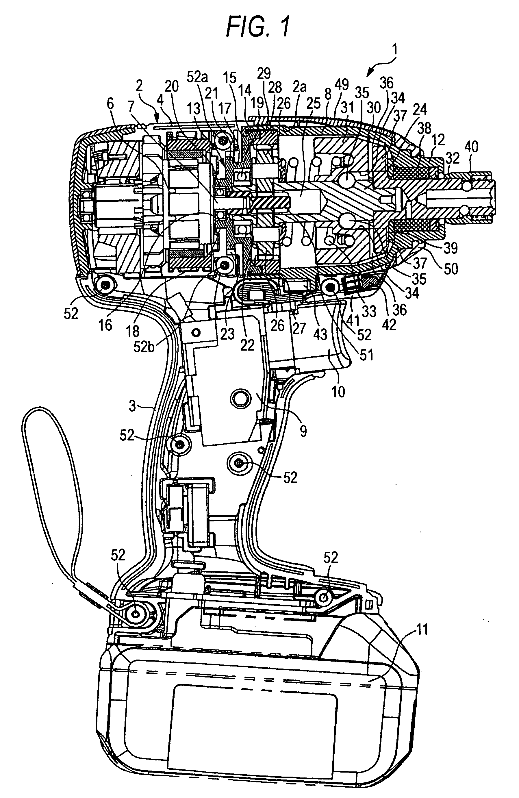
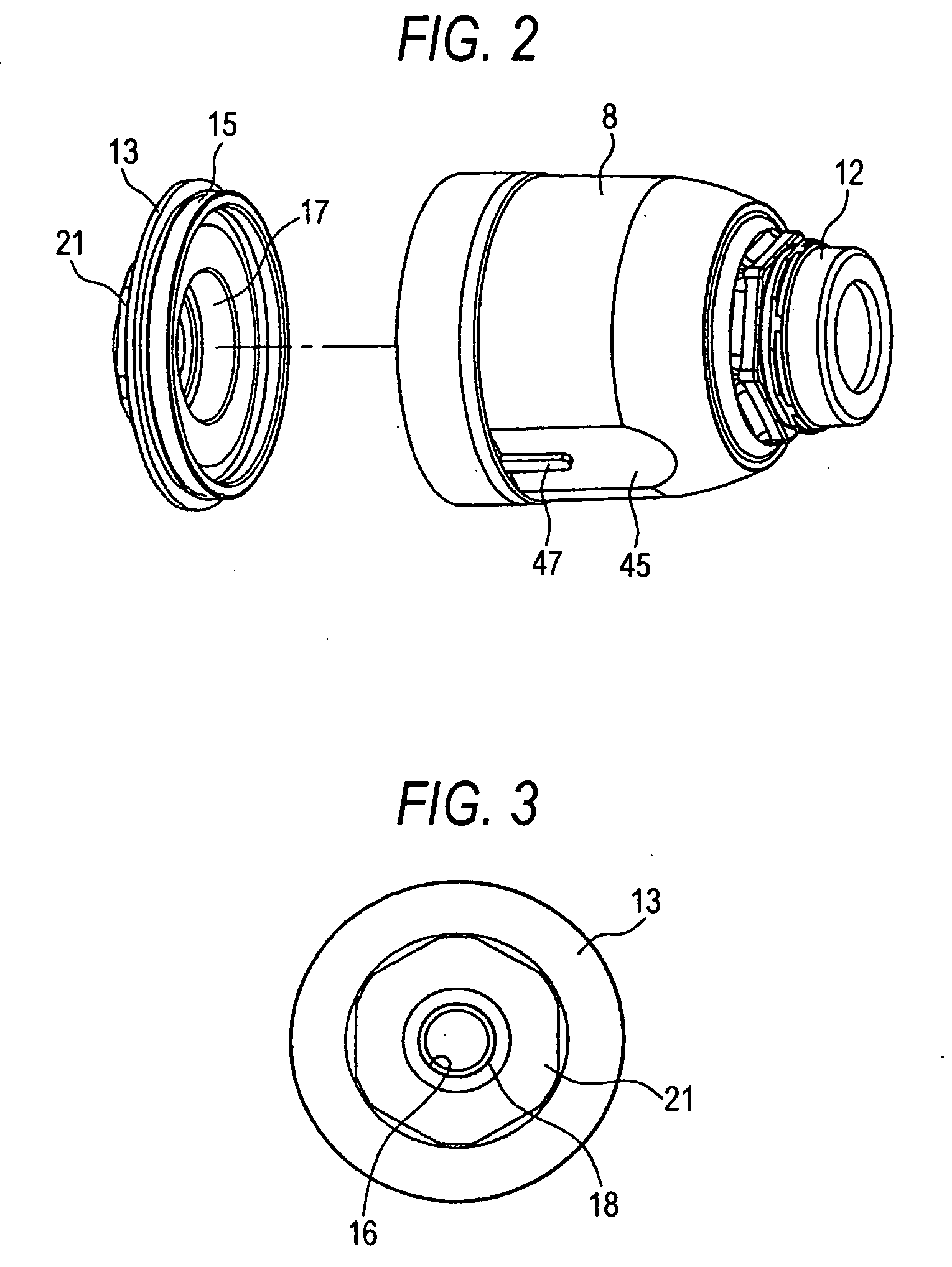
[0034] The hammer casing 8 is a bell-shaped member cylindrical member. A cylinder 12 having a relatively small diameter is formed at a front end of the hammer casing 8. A bearing box 13 shaped into a circular cap is integrally coupled to the hammer casing 8 so as to close a rear opening of the hammer casing 8. Specifically, a female thread 14 is formed on an inner periphery of the opened r...


PUM


Abstract

A housing body has a recess. A motor is housed in the housing body at a rear side of the recess. A hammer casing houses a rotatable spindle and an impact mechanism operable to convert the rotation of the spindle into intermittent impact actions in a first direction which is a circumferential direction of the spindle, and has an opened rear end. The hammer casing is mounted in the recess. A disk-shaped member is coupled to the hammer casing so as to close the opened rear end and to rotatably support the spindle. The disk-shaped member has a through hole receiving an output axis of the motor, thereby causing the output axis of the motor to couple with the spindle to transmit a rotation of the motor to rotate the spindle. A first engagement member is formed on an outer face of the disk-shaped member. A second engagement member is formed on an inner face of the recess and engaging with the first engagement member so as to restrict a movement of the hammer casing in a second direction parallel to a rotation axis of the spindle. A third engagement member is formed on an outer face of the hammer casing. A fourth engagement member is formed on an inner face of the housing body and engaging with the third engagement member so as to restrict a movement of the hammer casing in the first direction.

Description

BACKGROUND OF THE INVENTION [0001] The present invention relates to an impact tool in which a hammer casing installed with an impact mechanism is mounted on a front section of a housing body housing a motor. [0002] For example, Japanese Patent Publication No. 2003-145439A discloses an impact driver in which an internal gear casing and a hammer casing are mounted on a front section of a housing body which houses a motor. In the hammer casing, an impact mechanism is installed. This impact mechanism comprises: a spindle operable to rotate to transmit a power from an output axis of the motor by way of a planetary reduction gear mechanism; a hammer coupled to an outer periphery of the spindle so as to be movable in an axial direction of the spindle and so as to rotate together with the spindle; and an anvil disposed in a front side of the hammer so as to project toward a front side of the hammer casing. The hammer is urged toward the anvil by a coiled spring so that an engaging claw prov...

Claims


Application Information

Patent Timeline
IPC IPC(8): B25D11/00
CPCB25B21/02
Inventor NAGASAKA, HIDENORIKIMURA, TAKUJIMIYASHITA, KATSUSHI
Owner MAKITA CORP
Why Eureka
Try Eureka