Apparatus for gathering signatures along a conveying section of a circulating conveyor

a technology for conveying sections and apparatuses, which is applied in the direction of lighting and heating apparatus, furnace components, pile separation, etc., can solve the problems of loosely fitted together signature components being displaced relative to each other, reducing the quality of the final product, so as to avoid mutual displacement, avoid the effect of loss of quality and short structural length

Inactive Publication Date: 2006-08-17
MULLER MARTINI HLDG
View PDF9 Cites 36 Cited by
  • Summary
  • Abstract
  • Description
  • Claims
  • Application Information

AI Technical Summary

Benefits of technology

[0006] It is therefore an object of the present invention to design an apparatus of the aforementioned type, such that the signatures are conveyed carefully, without loss of quality, and to avoid mutual displacement of the signature components as well as blotting off, wherein the apparatus should also have a short structural length.

Problems solved by technology

The signatures, supplied by the delivery stations, are stacked precisely one above the other to form complete stacks of gathered signatures since a later alignment of a completed signature stack is not reliably possible.
One disadvantage of the above arrangement relates to the curved areas of transition in the movement path for the signatures, at the intake and discharge of the conveying path.
If a signature is subject to excessive bending stresses along the conveying path, the existing stiffness in the region of the longitudinal fold on the signature results in leaving traces of the bending which reduce the quality of the final product.
In the case of signatures with only one longitudinal fold, the additional danger exists that the loosely fitted together signature components are displaced relative to each other.
This disadvantage could be avoided by having a smaller inclination angle for the conveying path, but this would unfavorably affect the length of a delivery station which is not desirable for an apparatus having a plurality of delivery stations.
A further disadvantage results from the contact rollers, which are spring-loaded and press the upper belt section against the lower belt section, thereby exerting high Hertzian stresses onto the print products.

Method used


Image

  • Apparatus for gathering signatures along a conveying section of a circulating conveyor
  • Apparatus for gathering signatures along a conveying section of a circulating conveyor
  • Apparatus for gathering signatures along a conveying section of a circulating conveyor

Examples


Embodiment Construction

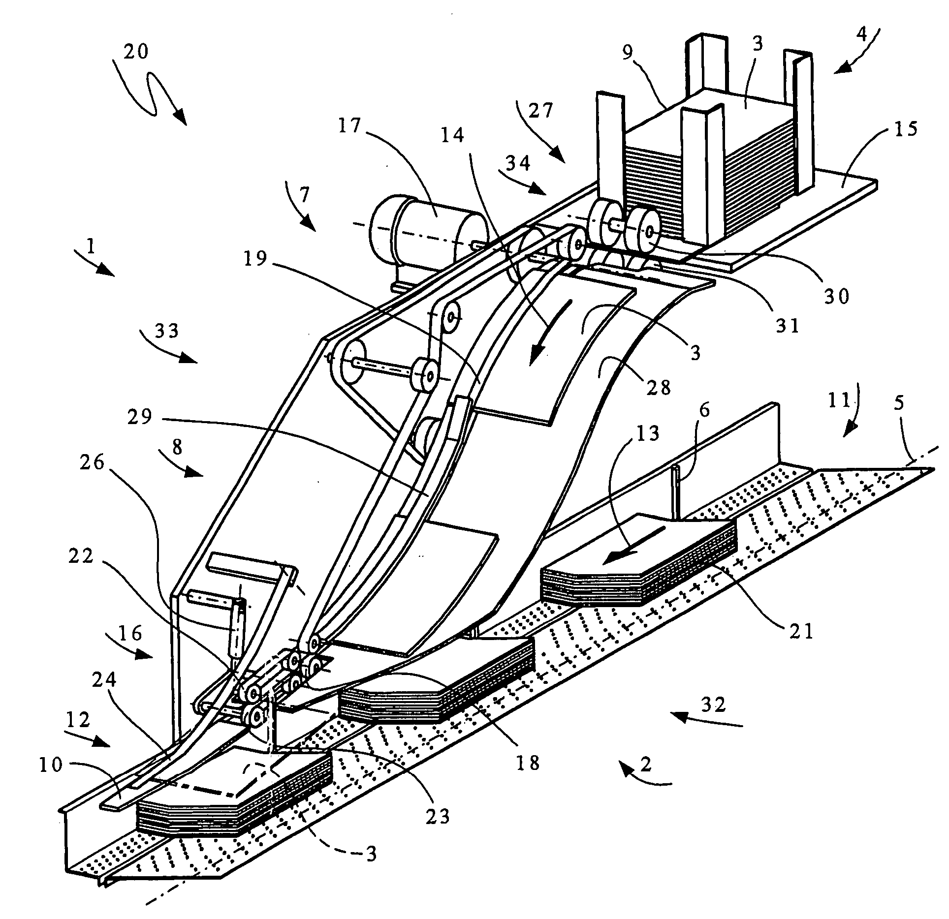
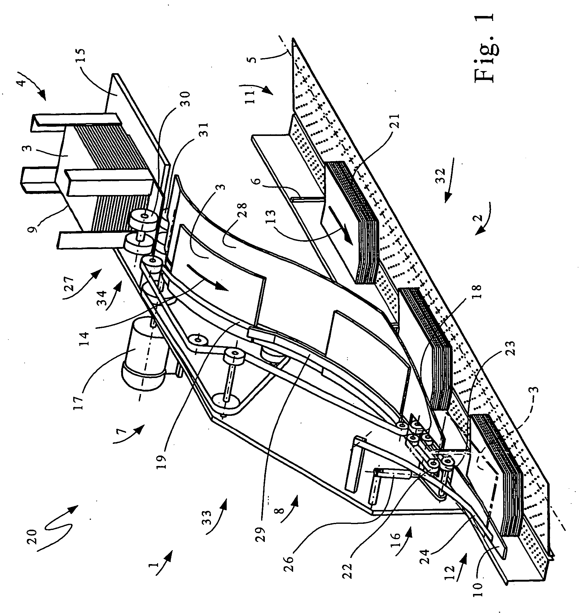
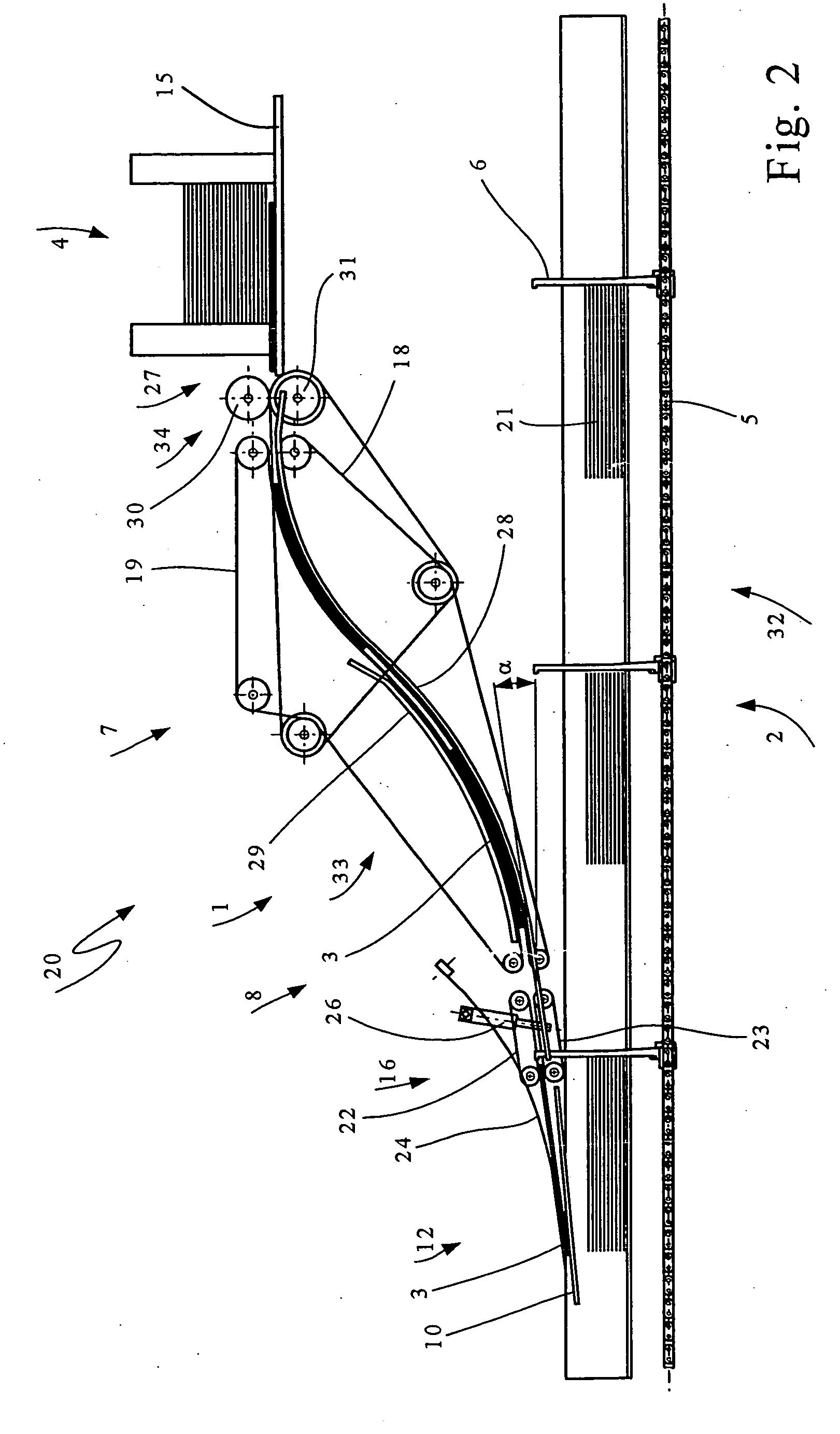
[0012] Referring to FIGS. 1-3, there is shown a delivery station 20 including a feeder 4, comprising a discharging location 27 for discharging signatures 3 and a delivery attachment 1 for supplying the signatures 3 to a conveying section 2. The conveying section 2 is formed by a slightly V-shaped gathering channel 11 (visible in FIGS. 1 and 3) and pushers 6 which are attached to a circulating traction mechanism 5, which push the continuously forming stacks of gathered signatures 21 in a conveying direction 13 through a gathering channel 11.

[0013] The signatures 3 to be processed are automatically or manually advanced to the feeder 4 to form a stack on a table 15. The signatures 3 are supplied by the feeder 4 to a conveying element 34, consisting of upper and lower withdrawing rollers 30 and 31, respectively, with the same timing as (i.e. in synchronism with) the conveying section 2 and / or conveyor 32. The delivery apparatus 1 comprises a conveying path 33 following conveying elemen...


PUM

PropertyMeasurementUnit
movementaaaaaaaaaa
flat angleaaaaaaaaaa
speedaaaaaaaaaa

Abstract

An apparatus is provided for gathering signatures along a conveying section of a circulating conveyor provided with spaced-apart pushers that are attached to a traction mechanism. The apparatus includes a delivery station adapted for being arranged along the conveying section. The delivery station includes a downward slanted conveying path wherein the signatures are supplied via the downward slanted conveying path from the delivery station to the conveyor approximately in synchronism with movement of the circulating conveyor. The conveying path includes a convex conveying section followed by a concave conveying section in the conveying direction for the signatures.

Description

CROSS-REFERENCE TO RELATED APPLICATION [0001] This application claims the priority of European Application No. 05405045.5, filed on Jan. 31, 2005, the subject matter of which is incorporated herein by reference. BACKGROUND OF THE INVENTION [0002] The invention relates to an apparatus for gathering signatures along a conveying section of a circulating conveyor, provided with successively spaced apart pushers that are attached to a traction mechanism and are moved past delivery stations which are arranged along the conveying section. In the process, the signatures are supplied by the delivery stations, operating at approximately the same speed as the circulating conveyor, via a downward pointing, slanted feeding path to the conveyor. [0003] Apparatuses of the aforementioned type are used, for example, for transporting signatures separated by feeders into the gathering channel of so-called gathering machines for perfect binding systems used in the graphics industry. Several delivery st...

Claims


Application Information

Patent Timeline
Patent Type & Authority Applications(United States)
IPC IPC(8): B65G49/00
CPCB65H5/068B65H5/34B65H5/38B65H29/14B65H29/70B65H31/28B65H33/18B65H39/02B65H39/055B65H2301/3112B65H2301/4352B65H2701/1932
Inventor MOSLI, URSBECHINGER, THOMAS
Owner MULLER MARTINI HLDG
Why Eureka
Try Eureka