Drum filter assembly

a filter assembly and drum filter technology, applied in the direction of moving filter element filters, filtration separation, separation processes, etc., can solve the problems of ponds that are eventually polluted, ponds that are almost impossible to clean, and stock kills

Inactive Publication Date: 2006-08-17
CUMMINSCORP LTD
View PDF31 Cites 14 Cited by
  • Summary
  • Abstract
  • Description
  • Claims
  • Application Information

AI Technical Summary

Benefits of technology

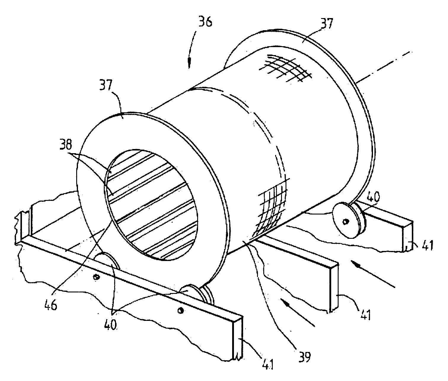
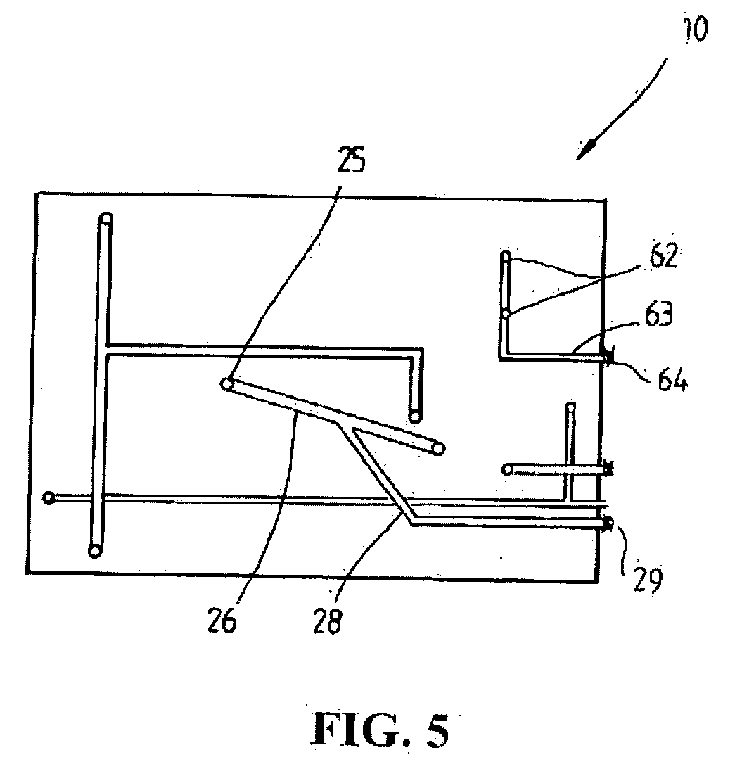
[0012] The inlet suitably also comprises a supply duct having one or more liquid outlets. The supply duct may extend longitudinally of the drum filter. In one form, the liquid outlets are preferably provided within the drum filter. The liquid outlets may be defined by radially extending duct members. The supply duct may have a baffle beyond the duct members to prevent liquid passing out of the drum filter. The hopper may communicate with an extending portion of the supply duct beyond the baffle which is connected to or communicates with a waste.

Problems solved by technology

The ponds however eventually become polluted because faeces, uneaten food and algae work their way to the bottom of the ponds.
This makes the ponds almost impossible to clean.
In addition large quantities of valuable water are required to keep these systems functional.
Other disadvantages are also associated with outdoor aquaculture systems.
For example pests can eat stock, adverse weather conditions such as floods can cause stock loss by washing the stock away and very hot weather can cause growth of algal blooms which can kill the stock.
Muddy waters or disturbed water can also cause the stock to have an unpalatable taste.
A disadvantage of the known systems is that the buildings or sheds housing the aquaculture system resemble a maze of pipes and plumbing as water is pumped between the system components such as tanks, filters, biological filters, foam fractionators, ultraviolet water treatment units and other water treatment components.
If the water is stopped for any length of time, it can be very detrimental to the fish stock as in times of heavy stock loading, the fish can only stay alive for around six minutes before fatalities begin to occur.
Another major drawback is that if a bearing or another major mechanical failure happens, removal the drum filter and all of the fittings is extremely time consuming and in many cases can lead to total stock losses.
Cleaning of the current drum filters in any event is difficult as easy access cannot be had to the interior of the drum.

Method used


Image

  • Drum filter assembly
  • Drum filter assembly
  • Drum filter assembly

Examples


Embodiment Construction

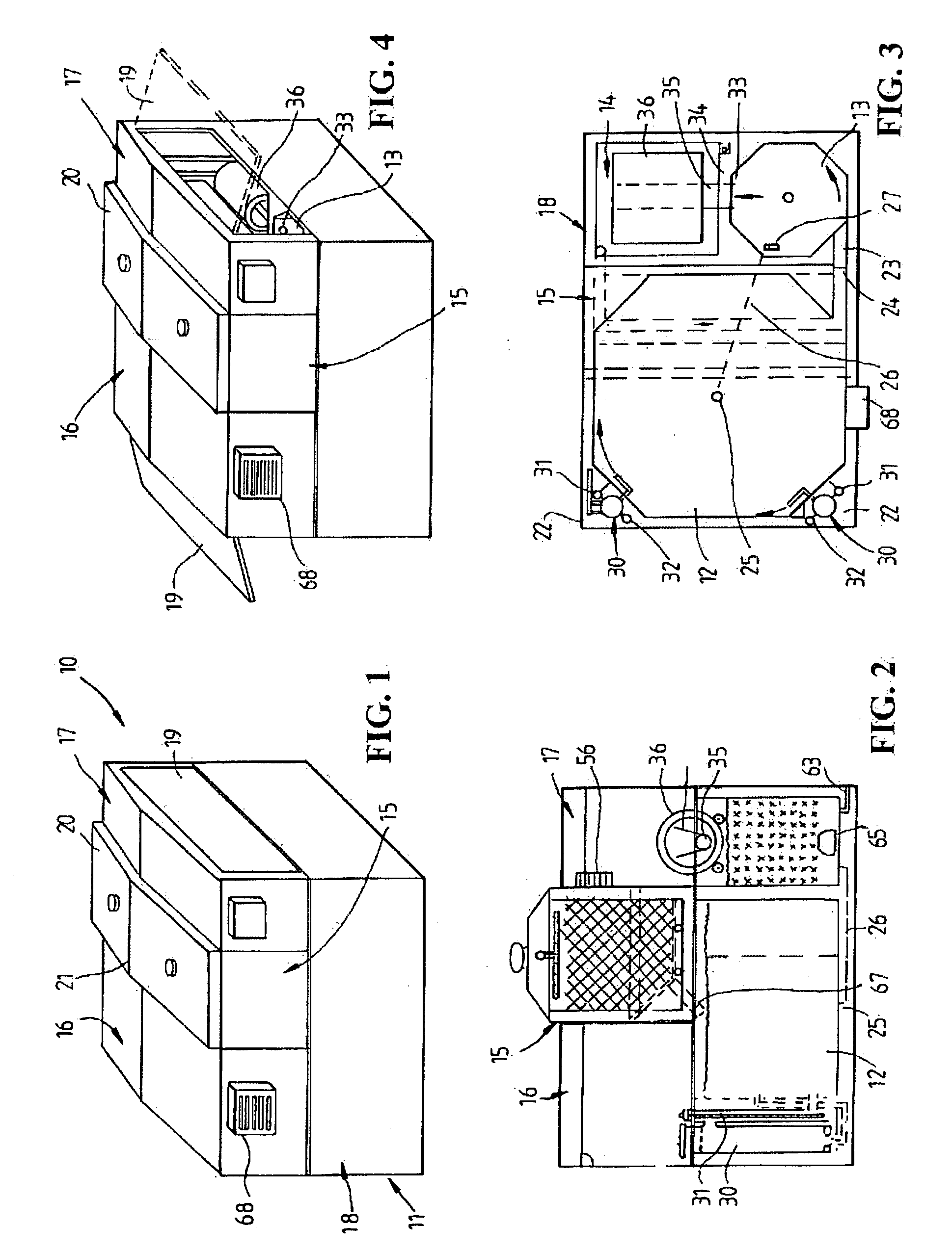
[0031] Referring to the drawings and firstly to FIGS. 1 to 4, there is illustrated an aquaculture system 10 in accordance with an embodiment of the invention in the form of a modular building 11 comprising and defining a main chamber 12 for holding fish or marine invertebrates, a swirl chamber 13 which serves as a primary filter and a biological filter-drum or screen filter chamber 14 of a secondary filter. The chambers 12, 13 and 14 have their bases at substantially at the same level however the water level in each chamber is controlled such that the level in chamber 14 is less than the level in chamber 13 and the level in chamber 13 is less than the level in chamber 12. This then allows flow of water from the main chamber to the swirl chamber 13 and then to the chamber 14 under the influence of gravity without pumping. The building module 11 also defines a biological filter tank 15 which is elevated and located above the main chamber 12. Opposite end integral hip roof and wall sec...


PUM

PropertyMeasurementUnit
rotationaaaaaaaaaa
length of timeaaaaaaaaaa
liquid outletsaaaaaaaaaa

Abstract

A drum filter assembly comprising a hollow drum filter having a longitudinal axis and an outer filter screen or mesh material, the drum filter being supported on external rollers for rotation about its longitudinal axis and an inlet for introducing liquid to be filtered into the interior of the drum filter. Rotation of the drum filter is effected by the liquid flowing into the drum filter. Alternatively, the drum filter may be driven by an external motor.

Description

CROSS REFERENCE TO RELATED APPLICATION [0001] This application is a divisional of U.S. application Ser. No. 10 / 487,210 filed Nov. 28, 2003.BACKGROUND OF THE INVENTION [0002] This invention relates to a drum filter assembly which is suitable for use in aquaculture systems but which may be used in any other water treatment application. [0003] Aquaculture has commonly been conducted by growing fish, prawns and other marine invertebrates in outdoor ponds. The ponds however eventually become polluted because faeces, uneaten food and algae work their way to the bottom of the ponds. This makes the ponds almost impossible to clean. In addition large quantities of valuable water are required to keep these systems functional. Other disadvantages are also associated with outdoor aquaculture systems. For example pests can eat stock, adverse weather conditions such as floods can cause stock loss by washing the stock away and very hot weather can cause growth of algal blooms which can kill the st...

Claims


Application Information

Patent Timeline
Patent Type & Authority Applications(United States)
IPC IPC(8): E04H4/12A01K63/00A01K63/04B01D24/46B01D33/06B01D33/15B01D33/27B01D33/44B01D33/58B01D35/027C02F1/24C02F1/32C02F1/78C02F3/06
CPCA01K63/00A01K63/04A01K63/042Y10S210/905B01D33/11A01K63/045B01D33/48Y02W10/37A01K61/10A01K61/59
Inventor CUMMINS, IAN GEOFFREY
Owner CUMMINSCORP LTD
Why Eureka
Try Eureka