
Operating current modifying device and method

a technology of operating current and modifying device, which is applied in the direction of computing operations for integration/differentiation, instruments, optical beam sources, etc., can solve the problems of insufficient precision control of output power, easy temperature influence on power generating element of electric device, and inability to correctly generate output power

Active Publication Date: 2006-08-17
TIAN HLDG
View PDF4 Cites 3 Cited by
  • Summary
  • Abstract
  • Description
  • Claims
  • Application Information

AI Technical Summary

Benefits of technology

[0004] The power generating element of an electric device is easily affected by temperature. For example, the performance and accurate of the electric device may be variant due to the thermal factor. In order to control the power generating element at different temperatures, a proper control module must be designed to modify the affection resulted from the thermal factor.

Problems solved by technology

The power generating element of an electric device is easily affected by temperature.
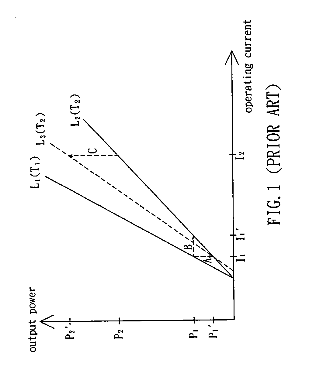
Thus, the power generating element does not correctly generate the output power at the power P2 and the output power is not precisely controlled at the temperature T2.
If the threshold current is ineffectual, the error caused by the prior technique is not obvious.
However, if the threshold current is effectual or the output power is to be controlled more precisely, the error caused by the operating current calculated according to the prior technique is inevitable.

Method used


Image

  • Operating current modifying device and method
  • Operating current modifying device and method
  • Operating current modifying device and method

Examples


Embodiment Construction

[0028] The present invention will be apparent from the following detailed description, which proceeds with reference to the accompanying drawings, wherein the same references relate to the same elements.

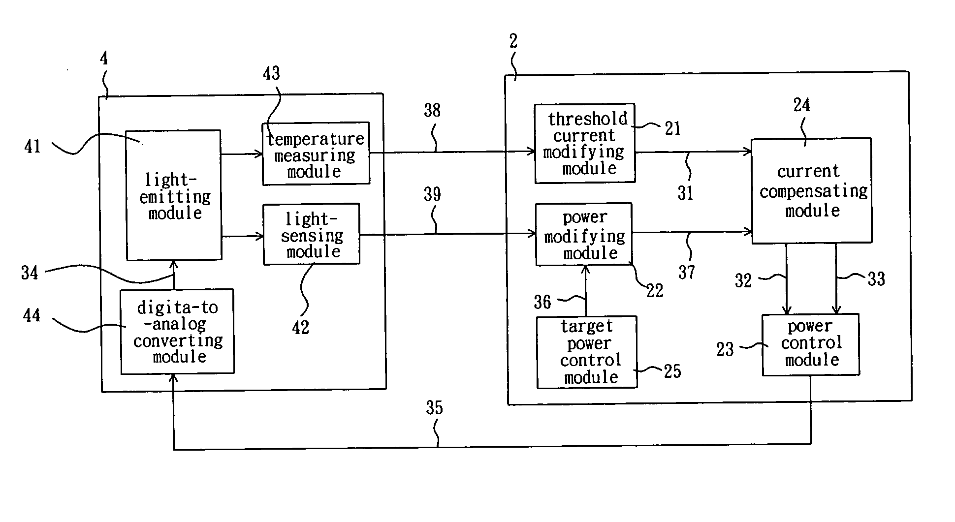
[0029] Referring to FIG. 2, an operating current modifying device 2 is provided for a power generating element. The power generating element may be an optical pickup head 4. The optical pickup head 4 includes a light-emitting module 41, a light-sensing module 42, a temperature measuring module 43, and a digital-to-analog converting module 44.

[0030] In the optical pickup head 4, when an operating current 34 is larger than a threshold current of the light-emitting module 41, the operating current 34 drives the light-emitting module 41 to generate an output power. The threshold current is related to a temperature of the light-emitting module 41.

[0031] Generally speaking, the light-emitting module 41 is implemented with a laser diode, so that the temperature and the threshold current ...


PUM


Abstract

An operating current modifying device is provided for a power generating element. The power generating element generates an output power when the operating current is larger than a threshold current in the power generating element. A functional relationship is between the threshold current and the temperature of the electrical device. The operating current modifying device includes a threshold current modifying module, a power modifying module, a current compensating module, and a power control module. The threshold current modifying module receives a temperature signal from the power generating element to output a threshold current modifying signal according to the temperature signal and the functional relationship. The power modifying module receives a power feedback signal from the power generating element and a target power signal to output an operating current modifying signal. The current compensating module receives the threshold current modifying signal and the operating current modifying signal to distribute the operating current modifying signal into an operating current compensating signal and a threshold current compensating signal. The power control module receives the operating current compensating signal and the threshold current compensating signal to adjust the operating current.

Description

BACKGROUND OF THE INVENTION [0001] 1. Field of Invention [0002] The invention relates to an operating current modifying device and an operating current modifying method, and, in particular, to an operating current modifying device and an operating current modifying method, which are applicable to an optical disk drive. [0003] 2. Related Art [0004] The power generating element of an electric device is easily affected by temperature. For example, the performance and accurate of the electric device may be variant due to the thermal factor. In order to control the power generating element at different temperatures, a proper control module must be designed to modify the affection resulted from the thermal factor. [0005] In order to control the output power of the power generating element at different temperatures, a proper control module is designed in the power generating element. Herein, a power feedback signal, which is generated when the power generating element generates the output ...

Claims


Application Information

Patent Timeline
IPC IPC(8): G06G7/18G06F7/64
CPCG11B7/00G11B7/126
Inventor LAI, RONNIECHEN, RONALD
Owner TIAN HLDG
Learn More