Planar light source unit

Active Publication Date: 2006-08-17
CITIZEN ELECTRONICS CO LTD
View PDF4 Cites 66 Cited by
  • Summary
  • Abstract
  • Description
  • Claims
  • Application Information

AI Technical Summary

Benefits of technology

[0029] With the above-mentioned structure, it is possible to uniformize the brightness of the illumination light within the light guiding plate and increase the entire brightness level by properly varying the anisotropic diffusion light intensity on the anisotropic diffusing surface of the light guiding plate, without uneven anisotropic diffusion light intensity which occurs in conventional planar light source units. For example, in a light guiding plate, by increasing the intensity of the anisotropic diffusion light in the vicinity of the LEDs and reducing the intensity of the anis

Problems solved by technology

However, the above-mentioned planar light source unit has problems as follows.
In this way, on the whole, there is a problem that it is difficult to adjust the directions of the light e

Method used


Image

  • Planar light source unit
  • Planar light source unit
  • Planar light source unit

Examples


first embodiment

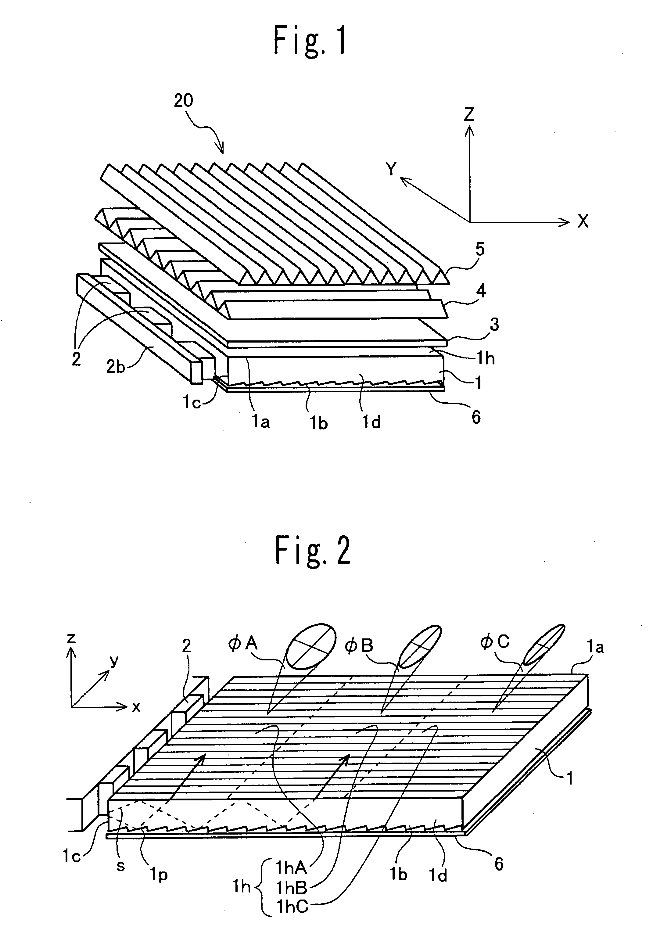
[0069] FIGS. 1 to 9 illustrate a planar light source unit according to the present invention.

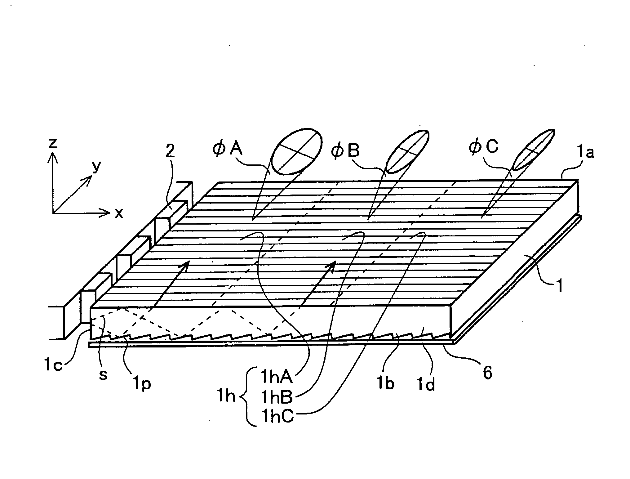
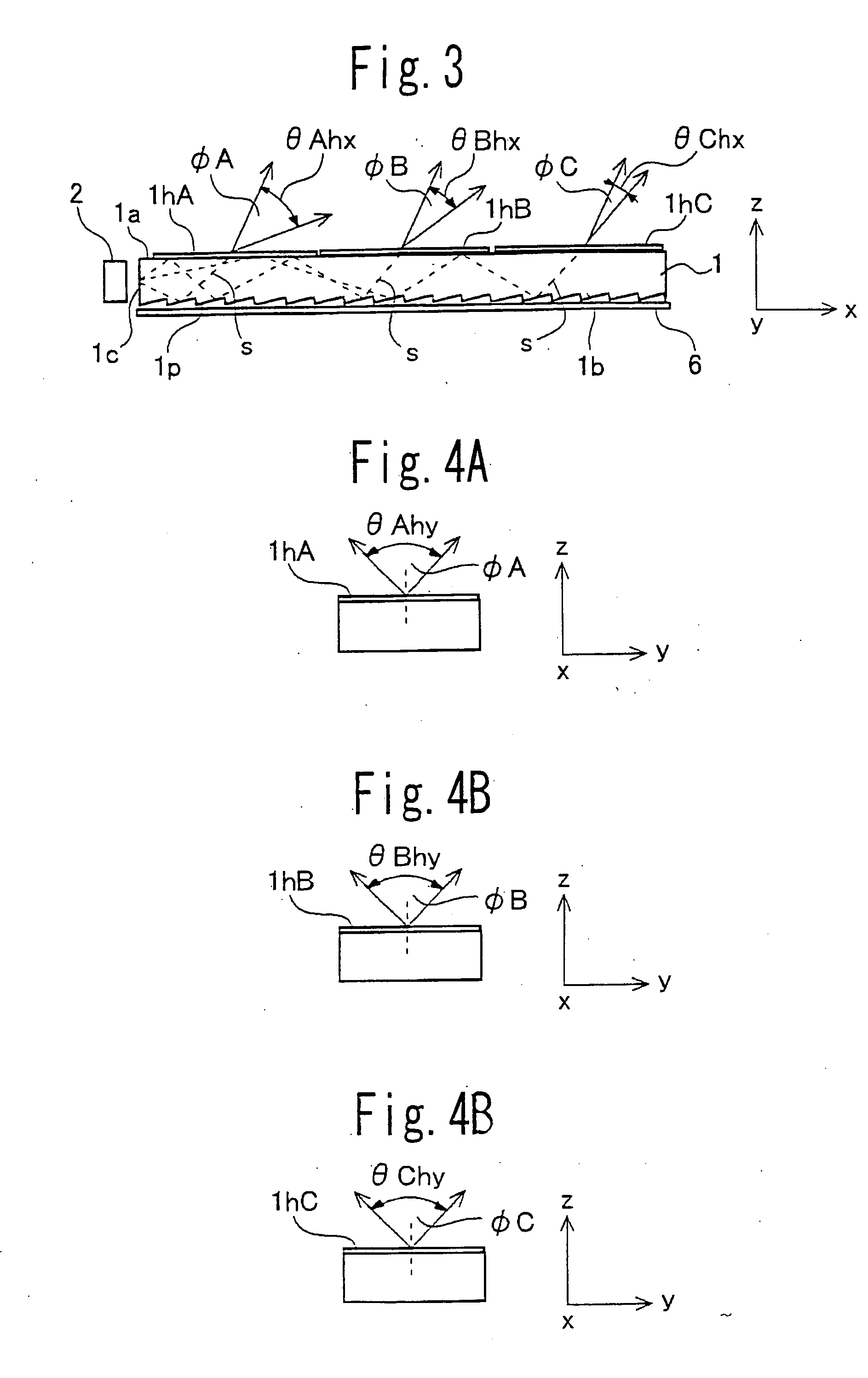
[0070] The planar light source unit 20 in the first embodiment includes a light guiding plate 1 and a light emitting source 2 for supplying light to the light guiding plate 1, as shown in FIG. 1. The light guiding plate 1 is formed from, for example, a rectangular plate and has an upper surface 1a, a lower surface 1b, side surfaces 1c and end surfaces 1d (see FIG. 1). The light emitting source 2 comprising at least one light emitting diode (LED) is disposed to face an incident surface formed on one side surface 1c of the light guiding plate 1 in the illustrated embodiment. The LEDs 2 are attached to an LED substrate 2b and are disposed at predetermined intervals.

[0071] In the first embodiment, for example, a diffusion plate 3, a Px prismatic sheet 4, and a Py prismatic sheet 5 are laminated in turn on the upper surface of the light guiding plate 1. An object, for example, an LCD panel 7 is ...

second embodiment

[0113] Next, the present invention is explained.

[0114] FIGS. 10 to 13 illustrate a light guiding plate and an anisotropic diffusing surface provided on the light guiding plate, which are used for a planar light source unit according to the second embodiment. The light guiding plate 1 is the same in shape as that in FIG. 2. As shown in FIG. 10, the anisotropic diffusing surface 11h is provided integrally on an upper surface 1a of the light guiding plate 1.

[0115] In other respects the structure of the planar light source unit according to the second embodiment is the same as for the planar light source unit 20 shown in FIG. 1.

[0116] As shown in FIGS. 10 and 11, anisotropic diffusion light φ11 is emitted from the anisotropic diffusing surface 11h. Here, an angular width of the diffusion light φ11 in the x-z plane and an angular width of the diffusion light φ11 in the y-z plane are set to be θhx1 and θhy1, respectively.

[0117] Throughout the entire light guiding plate 1, the angular w...

third embodiment

[0122] Hereinafter, the present invention is explained.

[0123] FIGS. 14 to 17D illustrate a light guiding plate and an anisotropic diffusing surface, which are used for a planar light source unit according to the third embodiment of the present invention.

[0124] The light guiding plate 1 is the same in shape as that in FIG. 2. As shown in FIGS. 14 and 15, the anisotropic diffusing surface 12h is provided integrally on an upper surface 1a of the light guiding plate 1.

[0125] In other respects the structure of the planar light source unit according to the third embodiment is the same as for the planar light source unit 20 shown in FIG. 1.

[0126] As shown in FIGS. 14 and 15, anisotropic diffusion light φ12 is emitted from the anisotropic diffusing surface 12h. Here, an angular width of the diffusion light φ12 in the x-z plane as shown in FIG. 15 and an angular width of the diffusion light φ12 in the y-z plane as shown in FIGS. 16A to 16C are set to be θhx2 and θhy2, respectively.

[0127]...


PUM


Abstract

A planar light source unit including a light guiding plate (1) having an anisotropic diffusing surface (1h) which emits anisotropic diffusion light, and a light emitting source (2) for supplying light to the light guiding plate, the anisotropic diffusing surface being formed into a shape configured to give a gradation of the anisotropic diffusion light intensity.

Description

CROSS-REFERENCE TO THE RELATED APPLICATION [0001] This application is based on and claims the priority benefit of Japanese Patent Application No. 2005-14918 filed on Jan. 24, 2005, the disclosure of which is incorporated herein by reference in its entirety. BACKGROUND OF THE INVENTION [0002] 1. Field of the Invention [0003] The present invention relates to a planar light source unit used as a backlight for illuminating a display such as a liquid crystal display (LCD) panel from back surface thereof. [0004] 2. Description of Related Art [0005] There have been known backlight devices comprising planar light source units as means for illuminating LCD panel or the like used in mobile terminal devices, laptop type computers or the like. [0006] This kind of planar light source unit has a structure as shown in FIGS. 22A to 22C (see, for reference, Japanese Patent Laid-Open 2003-337333, FIG. 17). [0007] As shown in FIGS. 22A and 22B, the planar light source unit 120 includes a light guiding...

Claims


Application Information

Patent Timeline
IPC IPC(8): F21V7/04F21S2/00F21V8/00F21Y101/02G02B5/02G02B6/00G02F1/13357
CPCG02B6/0038G02B6/0061G02B6/0068
Inventor OKUWAKI, DAISAKU
Owner CITIZEN ELECTRONICS CO LTD
Why Eureka
Try Eureka