Shroud Block with Enhanced Cooling

a technology of shield block and shield block, which is applied in the direction of liquid fuel engine, vessel construction, marine propulsion, etc., can solve the problems of reducing the efficiency of turbines, and achieve the effect of maximizing cooling efficiency and dedicated cooling

Active Publication Date: 2006-08-17
H2 IP UK LTD
View PDF7 Cites 27 Cited by
  • Summary
  • Abstract
  • Description
  • Claims
  • Application Information

AI Technical Summary

Benefits of technology

[0007] The present invention overcomes the shortfalls of the prior art by providing a shroud configuration that provides enhanced and dedicated cooling to previously un-cooled regions of the turbine shroud, specifically the shroud sidewalls. Furthermore, the circumferential cooling holes are spaced such that additional cooling air is directed to the highest temperature regions of the shroud in order to maximize the cooling efficiency.

Problems solved by technology

However, while it is necessary to cool the shroud segments, any air directed to cool the shroud segments does not pass through the turbine, thereby reducing the turbine efficiency.

Method used


Image

  • Shroud Block with Enhanced Cooling
  • Shroud Block with Enhanced Cooling
  • Shroud Block with Enhanced Cooling

Examples


Embodiment Construction

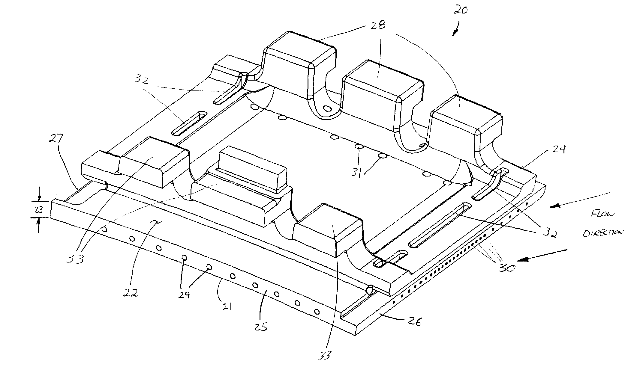
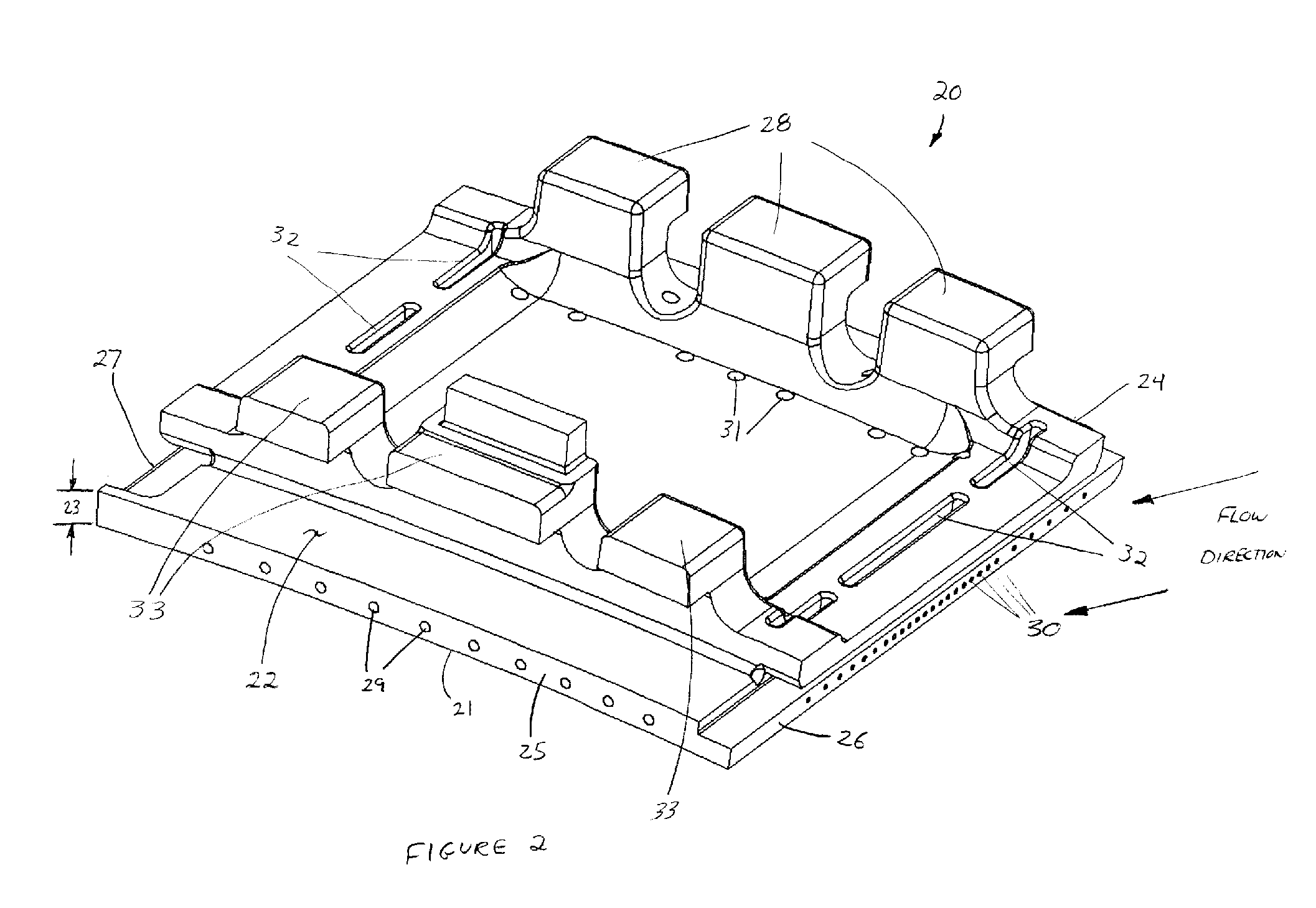
[0011] The preferred embodiment will now be described in detail with specific reference to FIGS. 2 and 3. A shroud 20 for surrounding a portion of a gas turbine engine flow path is shown in perspective view in FIG. 2 and in a section view in FIG. 3. Shroud 20 comprises a number of features including a first surface 21 having a first contour and a second surface 22 having a second contour with second surface 22 located radially outward of first surface 21 thereby establishing thickness 23 therebetween. First contour and second contour are defined by the diameter of the turbine enclosed by shrouds 20, and will therefore vary in size by design. Shroud 20 further comprises forward face 24 and aft face 25, which are spaced in axial relation and extend radially between first surface 21 and second surface 22. Extending generally axially between forward face 24 and aft face 25 and spaced in circumferential relation are first sidewall 26 and second sidewall 27. An additional feature of shrou...


PUM


Abstract

A shroud for surrounding a portion of a turbine flow path having improved cooling and durability is disclosed. The shroud includes a plurality of generally axial cooling holes spaced a substantially equal distance apart and a plurality of generally circumferential cooling holes oriented generally perpendicular to the generally axial cooling holes. The generally circumferentially cooling holes are spaced a non-uniform distance apart so as to provide cooling to selected portions of shroud sidewalls to lower shroud operating temperatures and improve shroud durability.

Description

DESCRIPTION BACKGROUND OF THE INVENTION [0001] This invention generally relates to gas turbine engines and more specifically to a shroud section that surrounds a stage of rotating airfoils in the turbine of a gas turbine engine. [0002] A gas turbine engine typically comprises a multi-stage compressor, which compresses air drawn into the engine to a higher pressure and temperature. A majority of this air passes to the combustors, which mix the compressed heated air with fuel and contain the resulting reaction that generates the hot combustion gases. These gases then pass through a multi-stage turbine, which drives the compressor, before exiting the engine. A portion of the compressed air from the compressor bypasses the combustors and is used to cool the turbine blades and vanes that are continuously exposed to the hot gases of the combustors. In land-based gas turbines, the turbine is also coupled to a generator for generating electricity. [0003] In the turbine section of the engine...

Claims


Application Information

Patent Timeline
Patent Type & Authority Applications(United States)
IPC IPC(8): F04D31/00
CPCF01D11/08F01D11/24F05D2240/11F05D2260/201
Inventor PARKER, DAVID G.MOORE, ROBERT P.ELLIS, CHARLES
Owner H2 IP UK LTD
Why Eureka
Try Eureka