Analysis apparatus and condenser

Inactive Publication Date: 2006-08-17
MITSUBISHI CHEM MEDIENCE
View PDF1 Cites 2 Cited by
  • Summary
  • Abstract
  • Description
  • Claims
  • Application Information

AI Technical Summary

Benefits of technology

[0029] According to the present invention, it is possible to enhance the positioning accuracy while detecting lights by means of simplifying the position adjusting of the light-sensitive detector and the analysis chip, and also enhance the a

Problems solved by technology

However, the conventional analysis apparatus such as the patent publication 1 has the following problems.
One is that the lack of positioning accuracy while detecting the lights and the instability of h

Method used


Image

  • Analysis apparatus and condenser
  • Analysis apparatus and condenser
  • Analysis apparatus and condenser

Examples


Example

1. First Embodiment

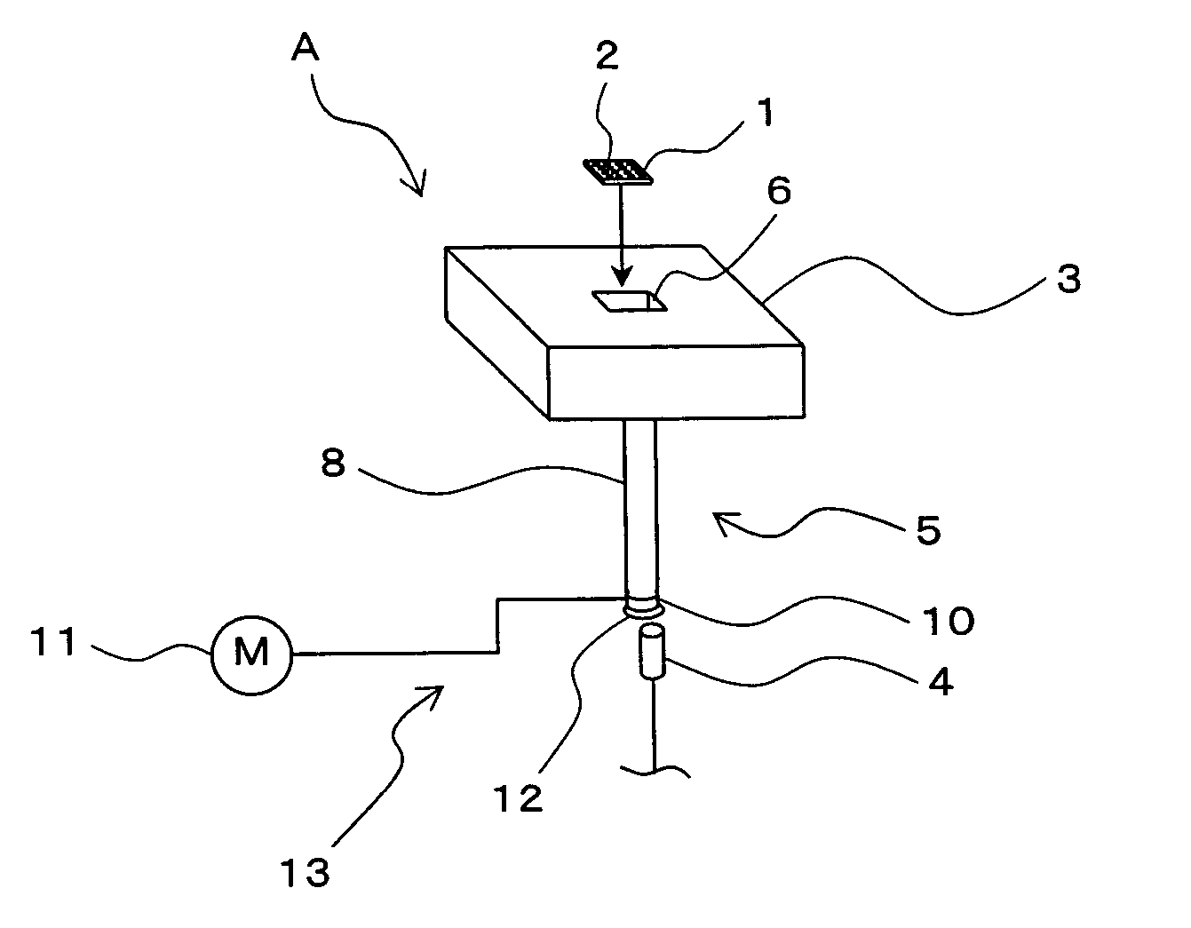
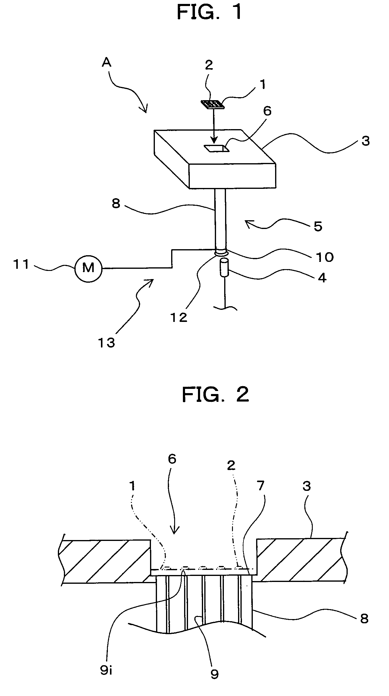
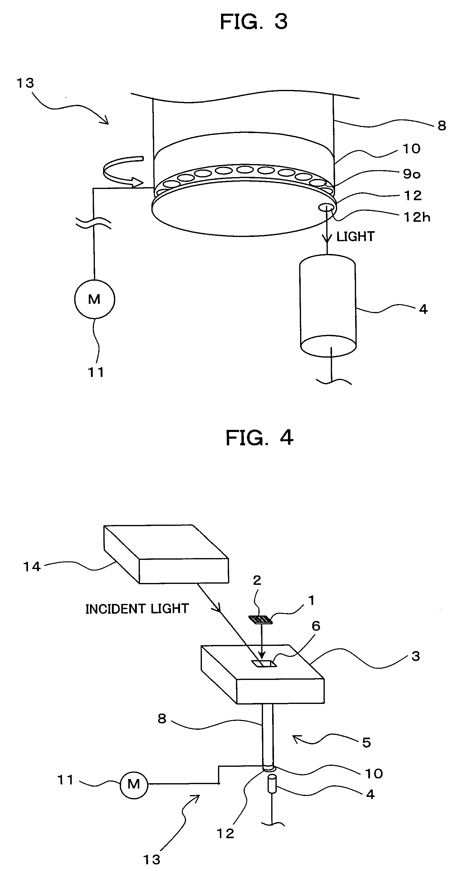
[0047] In the following, the first embodiment of the present invention is described with reference to FIGs. FIGS. 1-4 show the constructions of the embodiment. FIG. 1 is a schematic perspective view of an analysis apparatus according to the first embodiment. FIG. 2 is a sectional view of a chip holder used in the analysis apparatus. FIG. 3 is an enlarged perspective view of a rotating holder and its surroundings. FIG. 4 is a schematic perspective view of the analysis apparatus as a modification of the first embodiment.

[0048] The analysis apparatus A shown in FIG. 1 utilizes an analysis chip 1 for detecting lights coming from spots 2 formed plurally on the analysis chip 1. Each spot 2 has a specific material immobilized thereon. In this embodiment, “specific material” means a material that generates chemiluminescence through interaction with a reactant and thus “light from the spot 2” is a light generated as chemiluminescence. The portions of the analysis chip 1 ...

Example

2. Second Embodiment

[0073] In the following, the second embodiment of the present invention is described with reference to FIGs. FIGS. 5 and 6 show the constructions of the embodiment. FIG. 5 is a schematic perspective view of the analysis apparatus. FIG. 6 is an enlarged perspective view of a crank fiber and its surroundings. In FIGS. 5 and 6, components that are substantially the same as those in FIGS. 1-4 have the same reference letter as in FIGS. 1-4.

[0074] As illustrated in FIG. 5, the analysis apparatus B has the same basic constructions as the analysis apparatus A described in the first embodiment such as a chip holder 3 for holding the analysis chip 1 and a light-sensitive detector or a photomultiplier tube 4. The lights from the spots 2 on the analysis chip 1 held by the chip holder 3 are detected by the photomultiplier tube 4. A condenser 15 is provided to the analysis apparatus B in place of the condenser 5 to the analysis apparatus A. The other components of the appara...

Example

3. Third Embodiment

[0093] In the following, the third embodiment of the present invention is described with reference to FIGs. FIGS. 7-15 show the constructions of the embodiment. FIG. 7 is a schematic perspective view of the analysis apparatus. FIG. 8 is a vertical sectional view of a chip holder used in the analysis apparatus. FIG. 9 is a perspective view illustrating schematically a combination of optical fibers used in the analysis apparatus. FIG. 10 is an enlarged sectional view of the portion X of FIG. 8. FIGS. 11-15 are schematic perspective views of selecting units. In FIGS. 7-15, components that are substantially the same as those in FIGS. 1-6 have the same reference letter as in FIGS. 1-6.

[0094] The analysis apparatus C shown in FIG. 7, similar to the apparatus A and B described in the first and second embodiments, detects lights, using an analysis chip 1, coming from spots 2 formed plurally on the analysis chip 1. Each spot 2 has a specific material immobilized thereon....


PUM


Abstract

The object of the present invention is to provide an analysis apparatus that makes it possible to detect lights from a plurality of spots formed on an analysis chip without the lack of positioning accuracy while detecting the lights and the instability of holding the samples in spite of the downsized construction thereof. To achieve such an object as mentioned above, the analysis apparatus of the present invention for analyzing samples by means of detecting lights from a plurality of spots formed on an analysis chip so as to hold the samples comprising: a chip holder for holding the analysis chip; a light-sensitive detector for detecting lights from the spots; and a selectively light-transmitting unit for transmitting lights selectively from the desired spots to the light-sensitive detector, in a state where the analysis chip is held by the chip holder.

Description

BACKGROUND OF THE INVENTION [0001] 1) Field of the Invention [0002] The present invention relates to an analysis apparatus for analyzing samples in areas such as chemical analysis or biological analysis, and specifically, to an analysis apparatus for conducting the optical analysis by means of detecting lights from spots formed on an analysis chip and holding the samples thereon, and also relates to a condenser used in the analysis apparatus. [0003] 2) Description of the Related Art [0004] Currently, in areas such as the chemical analysis or the biological analysis, optical analyses including the fluorescence analysis, surface plasmon resonance analysis, chemiluminescence analysis, bioluminescence analysis, electrochemiluminescence analysis, and radioisotope analysis are conducted for analyzing various samples. [0005] In these analyses, lights generated from spots on an analysis chip, or reflection lights and transmitted lights from the spots irradiated are detected, generally in a ...

Claims


Application Information

Patent Timeline
IPC IPC(8): G01N21/00G01N21/25G01N21/47G01N21/64G01N21/59G01N21/78G01N35/00G01N35/02G01N37/00
CPCG01N21/253G01N35/00029G01N2035/00158
Inventor TAKAYAMA, HIDEHITOSAITOU, HARUYO
Owner MITSUBISHI CHEM MEDIENCE
Why Eureka
Try Eureka