Positive displacement heatstake apparatus and method thereof

Inactive Publication Date: 2006-08-17
NORTHPOINTE
View PDF10 Cites 5 Cited by
  • Summary
  • Abstract
  • Description
  • Claims
  • Application Information

AI Technical Summary

Benefits of technology

[0008] Another object of the invention is to utilize a plurality of ejector pins for stabilizing and holding in-place the thermoplastic part during the staking cycle, and yet further, the ejector pins are instrumental for positively ejecting the part once the staking cycle is complete, and the actuator portion returns to its starting position.
[0009] Yet another object of the invention is to provide a significantly faster system. The present invention allows an operator to bring the apparatus toward the thermoplastic part, heat the post within a few seconds maximum, and then stake. While some applications actually deform p

Problems solved by technology

This is usually very difficult since using one hot air gun with very low temperature control causes air to blow from one side.
If the post is too long, it is often just folded over instead

Method used


Image

  • Positive displacement heatstake apparatus and method thereof
  • Positive displacement heatstake apparatus and method thereof
  • Positive displacement heatstake apparatus and method thereof

Examples


Embodiment Construction

[0020] In the following description, like reference characters designate like or corresponding parts throughout the several views. Also, in the following description, it is to be understood that terms such as front, back, inside, outside, and the like are words of convenience and are not to be construed as limiting terms. Terminology used in this patent is not meant to be limiting insofar as devices described herein, or portions thereof, may be attached or utilized in other orientations. Referring in more detail to the drawings, the invention will now be described.

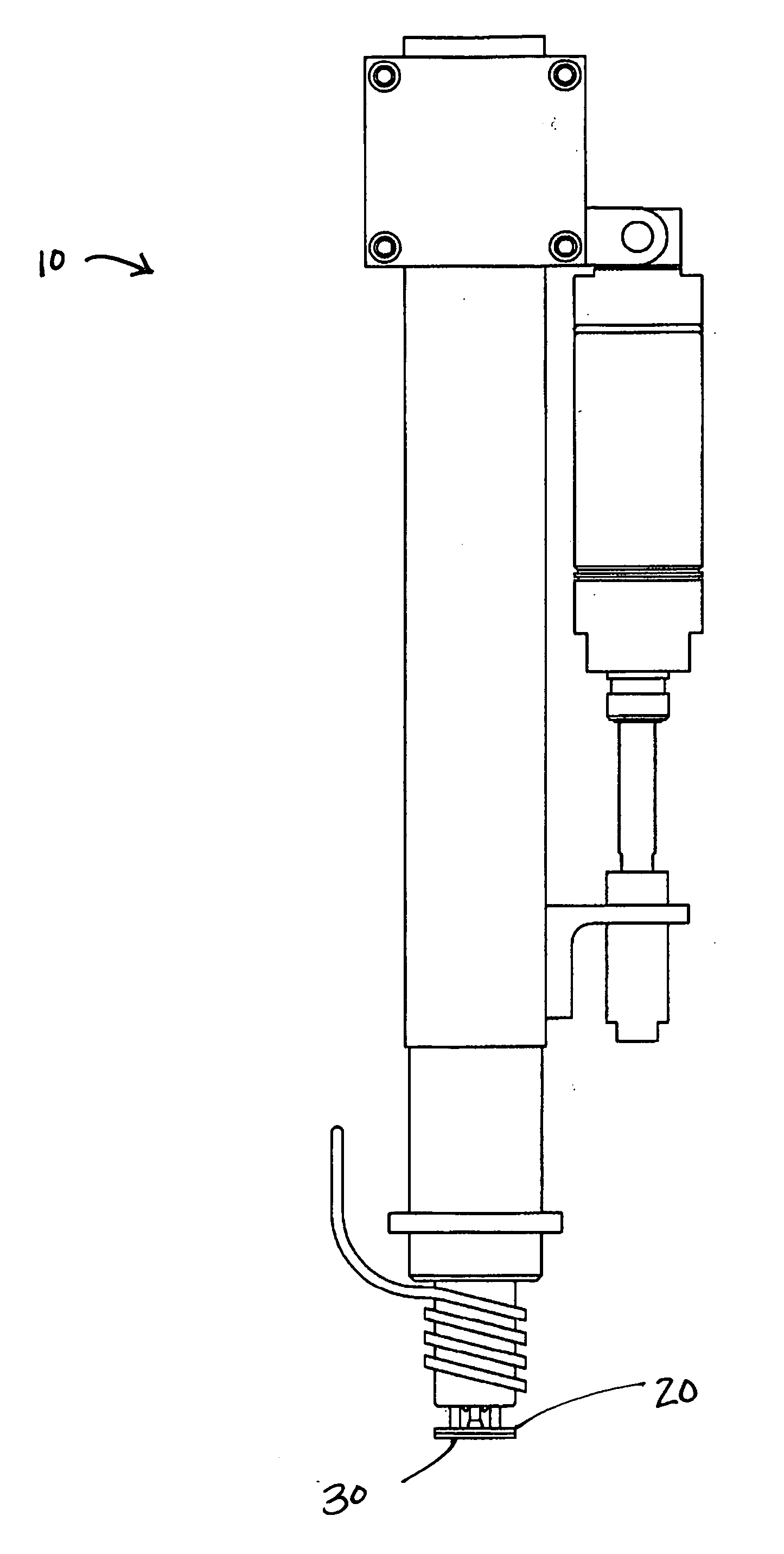
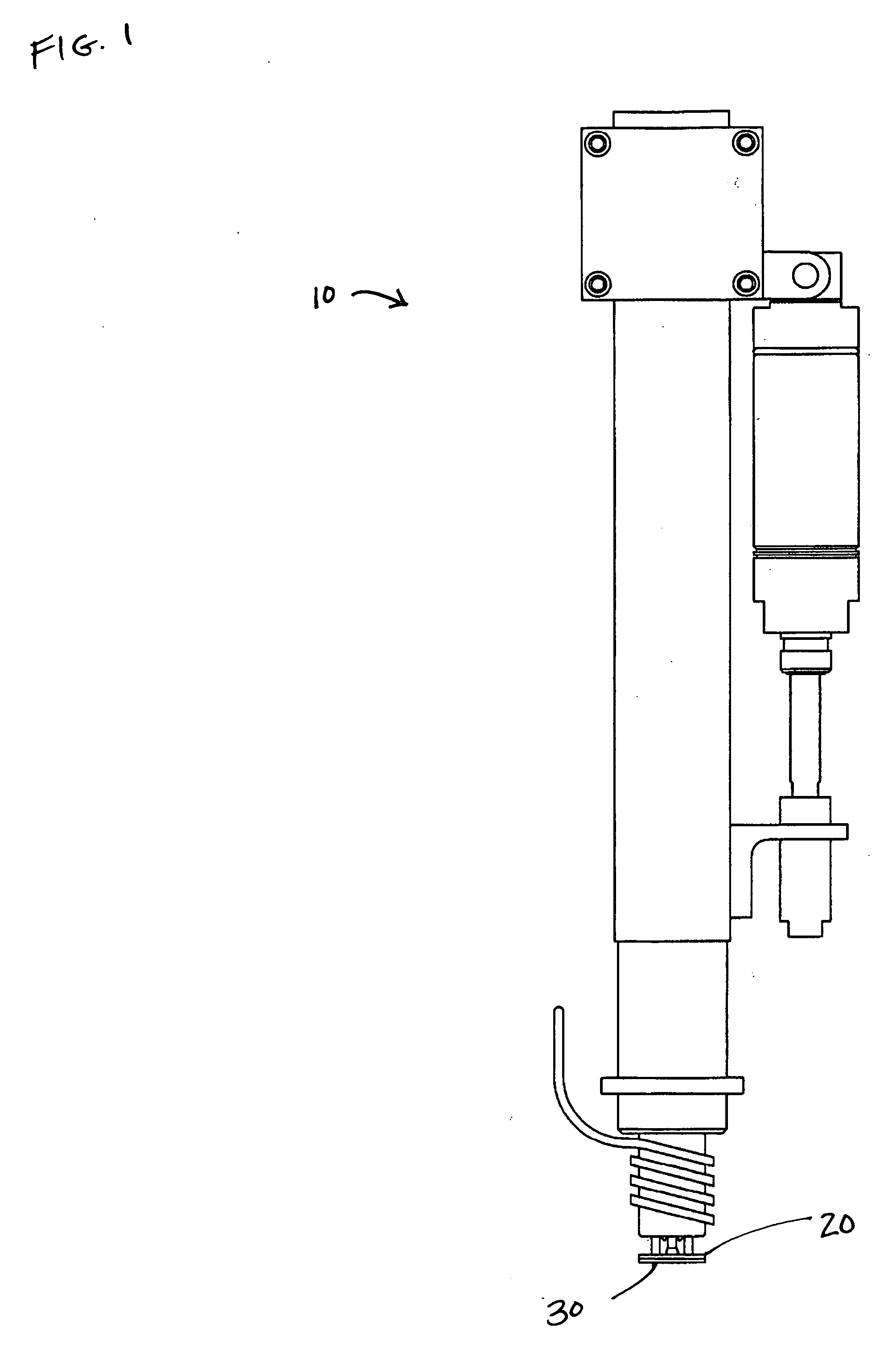
[0021] Referring now to FIG. 1, a heat staking apparatus 10 according to the present invention is shown positioned above a thermoplastic part 20. The thermoplastic part 20 is oriented in the cradle 30 portion of the heat staking apparatus 10. As is well known in the art, a post 22 formed of a thermoplastic material projects upwardly from the cradle 30. This new heat staking apparatus 10 works with just about any shape and...


PUM

PropertyMeasurementUnit
Temperatureaaaaaaaaaa
Electrical conductoraaaaaaaaaa
Thermal propertiesaaaaaaaaaa

Abstract

A heat staking method and apparatus for deforming thermoplastic parts and joining thermoplastic and dissimilar material parts to form an assembly is featured.

Description

BACKGROUND [0001] This present invention relates generally to heat staking machines, and is particularly directed to a positive displacement heat staking apparatus and the method of deforming thermoplastic using that apparatus. The literal definition of staking is the process of melting and reforming a thermoplastic post to lock it in place mechanically with a dissimilar material. Some of the most common thermoplastic materials include, but are not limited to ABS, polypropylene, polycarbonate, semi-crystallines, polymers, ABS / polycarbonate blends, and many engineering materials (even with as much as 30% filler). In the broadest sense, heat staking apparatuses are used to permanently fuse together a molded piece and metal assembly with a better torque strength than can be achieved with a simple threading technique. Common combinations include, but are not limited to, plastic to metal, rubber, glass or wood fiber products. [0002] For instance, almost every motor vehicle today has one ...

Claims


Application Information

Patent Timeline
IPC IPC(8): B29C65/18
CPCB29C65/606B29C66/80B29C66/8322B29C66/91231B29C66/91421B29C66/1122B29C66/21B29C66/41B29C66/71B29C66/81821B29C66/8242B29K2023/12B29K2055/02B29K2069/00
Inventor TRINKLE, CARLTON HUNT
Owner NORTHPOINTE
Why Eureka
Try Eureka