Passive micro fuel cell

a fuel cell and micro-chip technology, applied in the field of efficient and passive micro-chip fuel cells, can solve the problems of limited conventional rechargeable batteries, achieve the effects of boosting the efficiency of the reduction reaction, stably generating power, and easy venting of gas produced

Active Publication Date: 2006-08-17
NATIONAL TSING HUA UNIVERSITY
View PDF11 Cites 22 Cited by
  • Summary
  • Abstract
  • Description
  • Claims
  • Application Information

AI Technical Summary

Benefits of technology

[0015] The second objective of the present invention is to provide a micro fuel cell with a non-return pressure structure. The non-return pressure structure can prevent fuel delivery from a pressure blockage caused by the gas produced after the oxidation reaction.
[0016] The third objective of the present invention is to provide a micro fuel cell capable of separating gas from liquid. The gas and the liquid are separated from each other to be delivered by a surface with specific hydrophilic or hydrophobic treatment. Therefore, the fuel cell can stably generate power.
[0017] The fourth objective of the present invention is to provide a micro fuel...

Problems solved by technology

Conventional rechargeable batteries are limited by their weight and charging conven...

Method used


Image

  • Passive micro fuel cell
  • Passive micro fuel cell
  • Passive micro fuel cell

Examples


Embodiment Construction

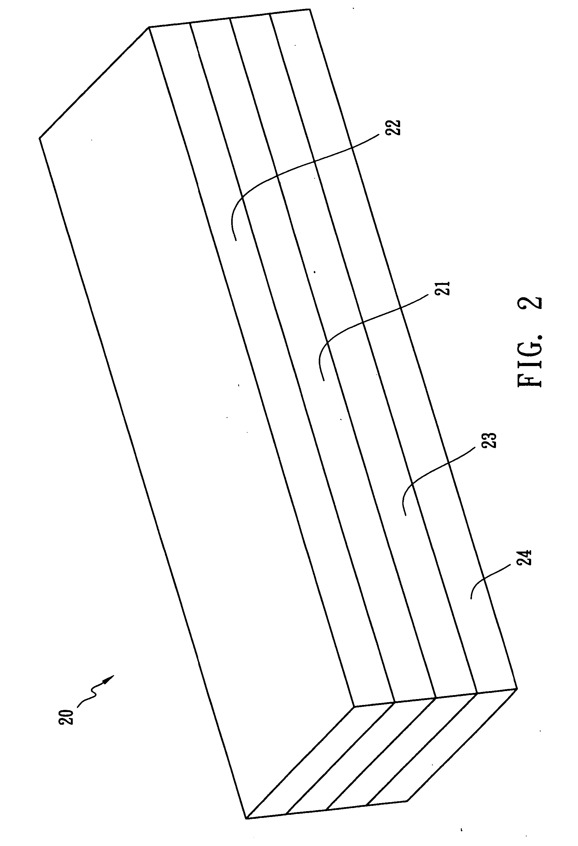
[0033]FIG. 2 is a perspective diagram of a passive micro fuel cell in accordance with the present invention. The micro fuel cell 20 comprises an anode plate 21, a condensation plate 22, a reaction plate 23 and a cathode plate 24 all fabricated on silicon substrates, wherein the reaction plate 23 is interposed between the anode plate 21 and the cathode plate 24.

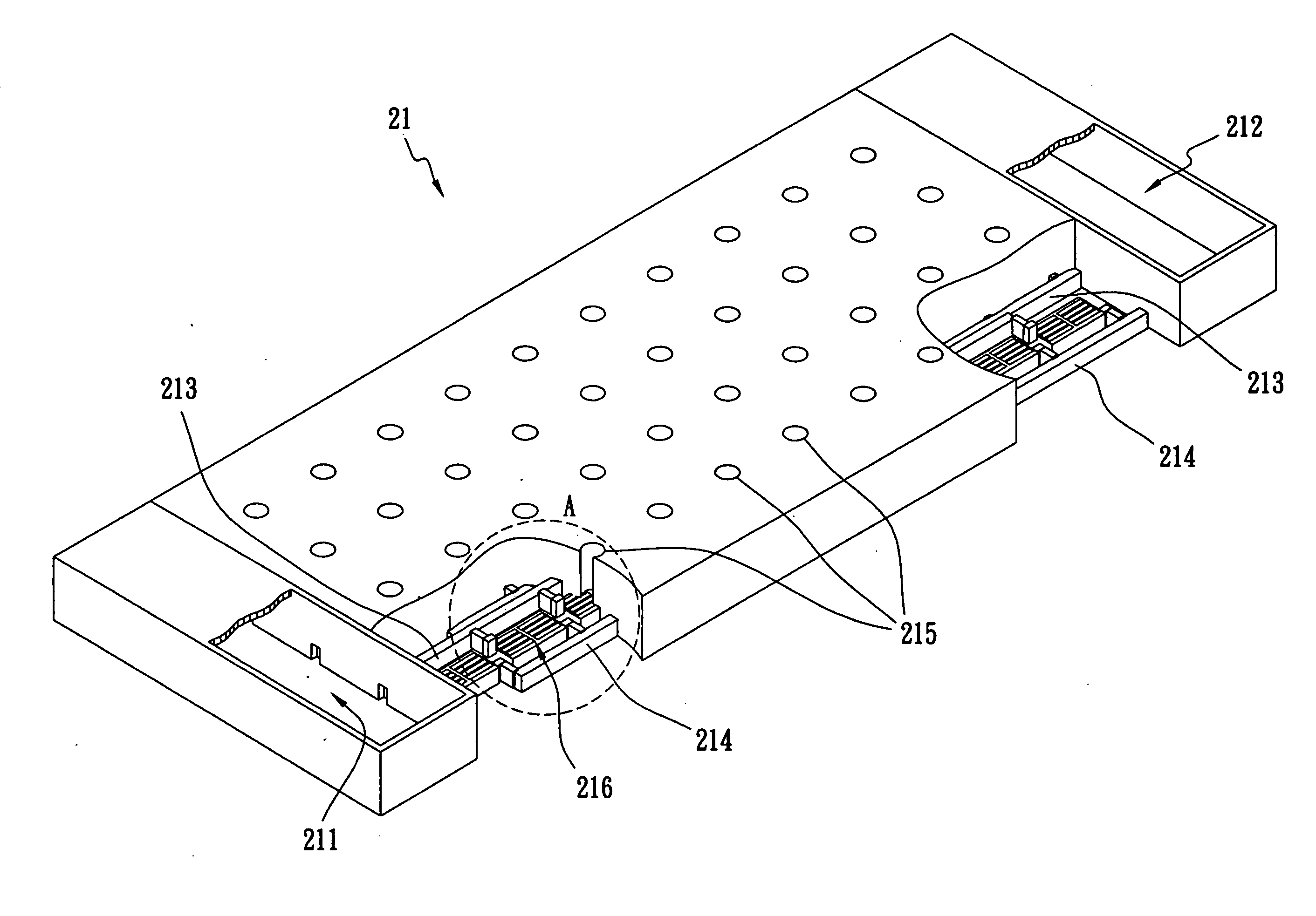
[0034] As shown in FIG. 3, a fuel tank 211 storing methanol dilute solution and a waste tank 212 collecting surplus methanol solution after an oxidation reaction are respectively placed either at two opposite sides or at the same side of the anode plate 21. A plurality of upper oxidation reaction rooms 216 is placed in the center of the anode plate 21 as an array arrangement. A delivery micro-channel 213 draws the methanol solution acting as a fuel from the fuel tank 211 and a waste liquid micro-channel 214 drains unreacted methanol solution to the waste tank 212. Both of the micro-channels 213 and 214 are separately formed o...


PUM


Abstract

An efficient and passive micro fuel cell includes an anode plate, a reaction plate, a cathode plate and a condensation plate. The anode plate draws a dilute solution of methanol from a fuel tank to delivery to a series of upper oxidation reaction room through micro-channels by thermal capillarity. The condensation plate separates carbon dioxide and vapor from each other. Meanwhile, the methanol solution is delivered to a plurality of lower oxidation reaction rooms. Protons pass through the inner walls of the reaction holes and a porous membrane layer and arrive in the lower reduction reaction rooms. The lower reduction reaction rooms and the lower oxidation reaction rooms have reaction holes whose inner walls have carbon nanotubes and catalysts. A plurality of upper reduction reaction rooms delivers oxygen for the reduction reaction and drains the reduced water at the same time.

Description

RELATED U.S. APPLICATIONS [0001] Not applicable. STATEMENT REGARDING FEDERALLY SPONSORED RESEARCH OR DEVELOPMENT [0002] Not applicable. REFERENCE TO MICROFICHE APPENDIX [0003] Not applicable. FIELD OF THE INVENTION [0004] The present invention relates to an efficient and passive micro fuel cell, and more particularly, to a fuel cell fabricated by a MEMS (Micro-Electro-Mechanical System) method. BACKGROUND OF THE INVENTION [0005] Currently, various kinds of portable electrical apparatuses such as notebook computers, personal digital assistants (PDA) and mobile phones need a miniature power generator. Conventional rechargeable batteries are limited by their weight and charging convenience for use, and therefore several power generators have been developed to replace them. Among these power generators, fuel cells fabricated by the MEMS method have been well and rapidly developed because they have the advantages of fast response, high heat dissipation and miniaturized size. [0006] Fuel ...

Claims


Application Information

Patent Timeline
IPC IPC(8): H01M8/02H01M4/96H01M8/04H01M8/24
CPCB82Y30/00H01M8/04186H01M8/04201H01M8/04291H01M8/1011H01M8/1097Y02E60/523Y02E60/50
Inventor TSENG, FAN-GANG
Owner NATIONAL TSING HUA UNIVERSITY
Why Eureka
Try Eureka