Screw feeder

Inactive Publication Date: 2006-08-24
ERDMAN AUTOMATION CORP
View PDF25 Cites 16 Cited by
  • Summary
  • Abstract
  • Description
  • Claims
  • Application Information

AI Technical Summary

Benefits of technology

[0016] The present invention overcomes many of the above-described limitations of prior art screw feeders. The present invention accommodates many different sizes and configurations of screws, and is easily adjusted to do so. In addition, the present invention minimizes clogging with shavings and other debris that may be mixed in with screws, and requires minimal tuning to operate efficiently. The present invention minimizes damage to pre-finished screws and has the ability to drop a screw, purge the line, or both independently or simultaneously.
[0022] In one embodiment the invention includes a fastener feeder for feeding fasteners that have a head and a shaft, the fastener feeder comprising: a substantially stationary bin to contain a plurality of fasteners; an inline feeder, comprising a feed track located higher than an upper level of fasteners in the bin and sloped downwardly and operably connected to a vibrator such that the vibrator vibrates the feed track to cause the fasteners to drop into the feed track so that the head is supported by the feed track and the shaft dangles below the head and to cause fasteners to travel down a slope in a queue; a lift gate to elevate a small number of fasteners from the plurality of fasteners in the bin to the feed track; and an escapement at a lower end of the in line feeder capable of isolating a single fastener from the lower end of the queue.

Problems solved by technology

This type of screw feeder tends to be somewhat fussy to operate, as it requires a great deal of tuning and adjustment to prepare the vibratory hopper to handle screws correctly.
Unfortunately, the reciprocation of the blade within the hopper of a blade type feeder has a tendency to abrade and chip the screw heads as they picked up by the blade.
The vibration of vibratory hopper screw feeders also tends to damage the finished portions of prefinished screws.
The chips or abrasions on the finished heads create an unacceptable cosmetic appearance.
In other words, it is desirable to be able to send a blast of compressed air down the line to carry the screw already in the line to its destination prior to placing another screw in the line, which otherwise may result in jamming of the automated screwdriver.
Many current systems are not capable of performing this act, and therefore must be disassembled and manually unclogged if a screw does not travel all the way to its destination through the tubular feed line.
Another problem with screw feeders arises from the fact that, commonly when screws are received from the manufacturer, various undesirable materials may accompany the screws in their package.
The undesirable material may include shavings created in the screw manufacturing process, screws that are damaged in the manufacturing process, and fragments of various packing material that may end up in with the screws during manufacture or shipping.
All of the above-described prior art screw feeders will tend to be clogged or otherwise disrupted in their operation by the presence of the various foreign material in the fasteners that are utilized.
Another limitation of existing screw feeders is that those that utilize a vibrating hopper tend to abrade the pre-finished portions of pre-finished screws, thus resulting in screws that have an unacceptable cosmetic appearance.
Another limitation of existing screw feeders is that they often require that the screw feeder be specifically designed for a specific size and configuration of screw; or, that the entire in line feed track be changed to accommodate a different-sized screw.
Finally, many existing vibratory hopper screw feeders are limited to a relatively small-capacity hopper, and therefore the hopper must be refilled with screws more often than would be desirable in a manufacturing process.

Method used


Image

  • Screw feeder
  • Screw feeder
  • Screw feeder

Examples


Embodiment Construction

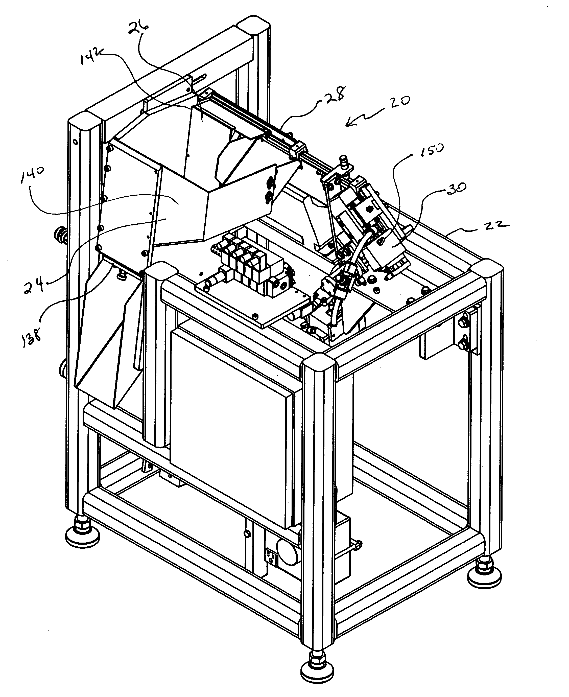
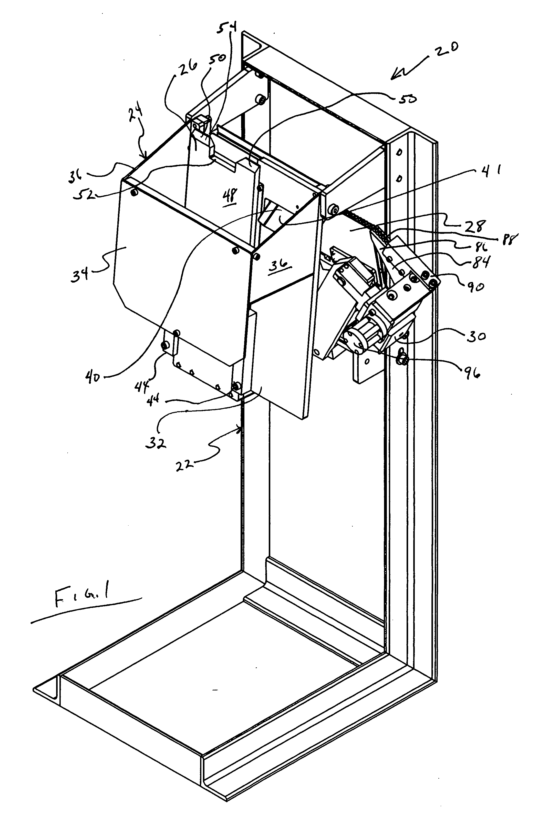
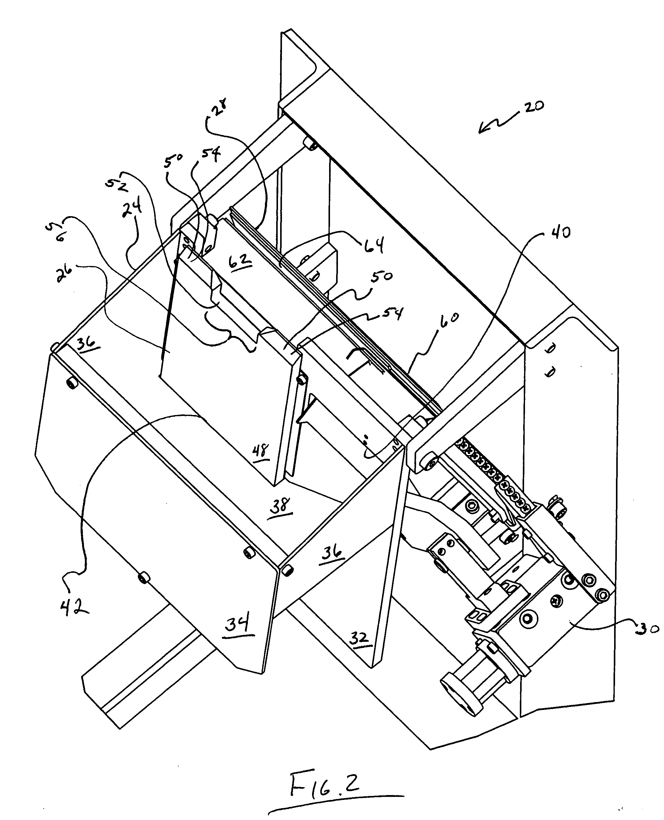
[0044] Referring to FIGS. 1 and 2, screw feeder 20 generally includes support frame 22, hopper 24, lift gate 26, in line feeder 28, and escapement 30. Support frame 22 supports hopper 24 and lift gate 26 together so that hopper 24 and lift gate 26 may be tiltably adjusted. Support frame 22 also supports in line feeder 28 and escapement 30 such that they may be adjusted in tilt to ensure proper gravity operation.

[0045] Hopper 24 generally includes backplate 32, frontplate 34, sides 36, and sloped bottom 38. Sloped bottom 38 is sloped to direct the contents of hopper 24 toward lift gate 26. Backplate 32 may be pierced by return aperture 40. Return aperture allows for the passage of return chute 41 through backplate 32. Sloped bottom 38 includes a cut out lift gate opening 42. Lift gate opening 42 is sized to allow close sliding passage of lift gate 26 therethrough. Hopper 24 is desirably formed of a durable abrasion resistant material such as sheet steel. Hopper 24 can be adjusted to...


PUM


Abstract

A fastener feeder for feeding fasteners that have a head and a shaft including: a substantially stationary bin, an inline feeder, with a feed track located higher than an upper level of fasteners in the bin and sloped downwardly and operably connected to a vibrator such that the vibrator vibrates the feed track to cause the fasteners to drop into the feed track so that the head is supported by the feed track and the shaft dangles below the head and to cause fasteners to travel down a slope in a queue; a lift gate to elevate a small number of fasteners from the plurality of fasteners in the bin to the feed track; and an escapement at a lower end of the in line feeder capable of isolating a single fastener from the lower end of the queue.

Description

CLAIM TO PRIORITY [0001] This application claims priority to U.S. Provisional Application 60 / 654,314 filed Feb. 18, 2005 entitled “Screw Feeder.”FIELD OF THE INVENTION [0002] The present invention relates to devices for collating and feeding of screws, nails and other like fasteners. More particularly, the invention relates to devices for collating and feeding screws to automated screwdrivers. BACKGROUND OF THE INVENTION [0003] Automated screwdrivers are commonly used in manufacturing facilities. An automated screwdrivers typically includes a pair of jaws for receiving and holding a screw while a screwdriver bit is advanced to engage the screw head and simultaneously rotate the screw while advancing it into a pre-drilled hole. Automated screwdrivers are commonly used to secure hardware to manufactured goods. [0004] Automated screwdrivers are commonly fed with screws via tubing made of polyethylene or another durable, flexible material. Prior to sending screws to an automated screwdr...

Claims


Application Information

Patent Timeline
IPC IPC(8): B23P11/00B23Q7/10
CPCB23P19/003Y10T29/49947Y10T29/53478B23P19/004
Inventor ERDMAN, RODNEYBERNS, ERICBLANK, CAMREN
Owner ERDMAN AUTOMATION CORP
Why Eureka
Try Eureka