Wheel alignment gauge

a technology of alignment gauge and wheel, which is applied in the direction of measuring devices, instruments, and using electrical means, can solve the problems of large space, high cost, and large size of existing wheel alignment machines, and achieve the effect of more accurate camber indication

Inactive Publication Date: 2006-08-24
MACKELVIE WINSTON
View PDF7 Cites 26 Cited by
  • Summary
  • Abstract
  • Description
  • Claims
  • Application Information

AI Technical Summary

Benefits of technology

[0004] Alignment arms with outboard lasers are magnetically attached to each plate. The arms have perpendicular locators to contact the front of the tire such that the outer ends of the alignment arms are at situated equally fore and aft. The alignment arms are adjusted horizontally using built-in levels. The set up is such that the outboard lasers beam across the the front of the vehicle onto respective target sheets centered on each laser. Thus if the wheels were in dead straight alignment, the two laser beams would be coincident and would not show on the targets. All other wheel alignment will show laser dots on the targets. The alignment arms may also be attached to the plates vertically locating on the top of the tire to project the laser beams across the top of the vehicle's hood for more accurate camber indication.

Problems solved by technology

Existing wheel alignment machines are large, expensive and require a large dedicated space (bay) and highly qualified operators.

Method used


Image

  • Wheel alignment gauge
  • Wheel alignment gauge
  • Wheel alignment gauge

Examples


Embodiment Construction

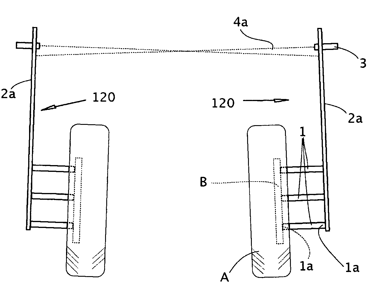
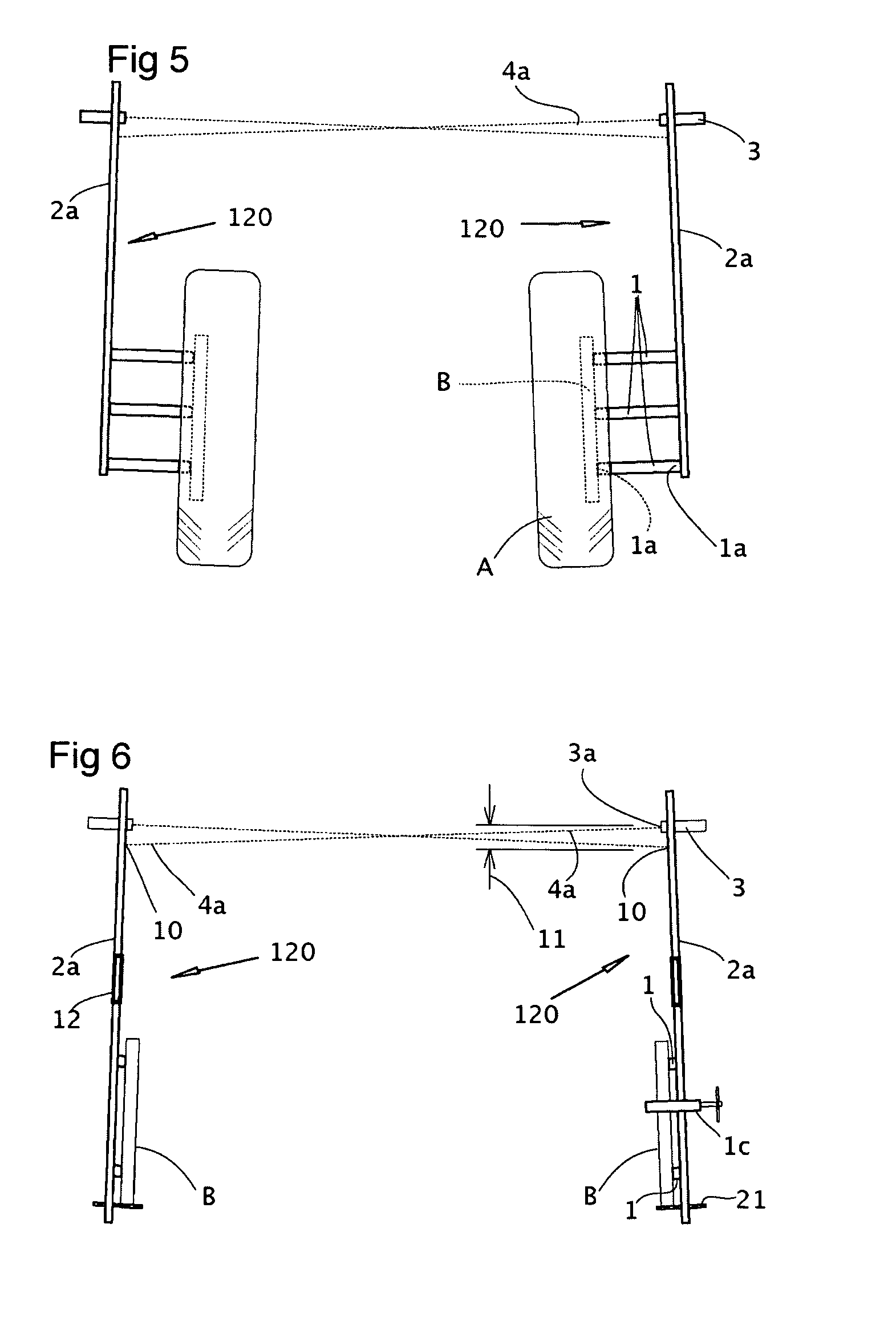
[0029] Vehicle wheels are factory aligned (actually misaligned) in the forward plane to have a specific degree of “toe” (misaligned to aim forwardly towards or away from each other) and in the vertical plane to have a specific degree of “camber” (misaligned to aim vertically towards or away from each other).

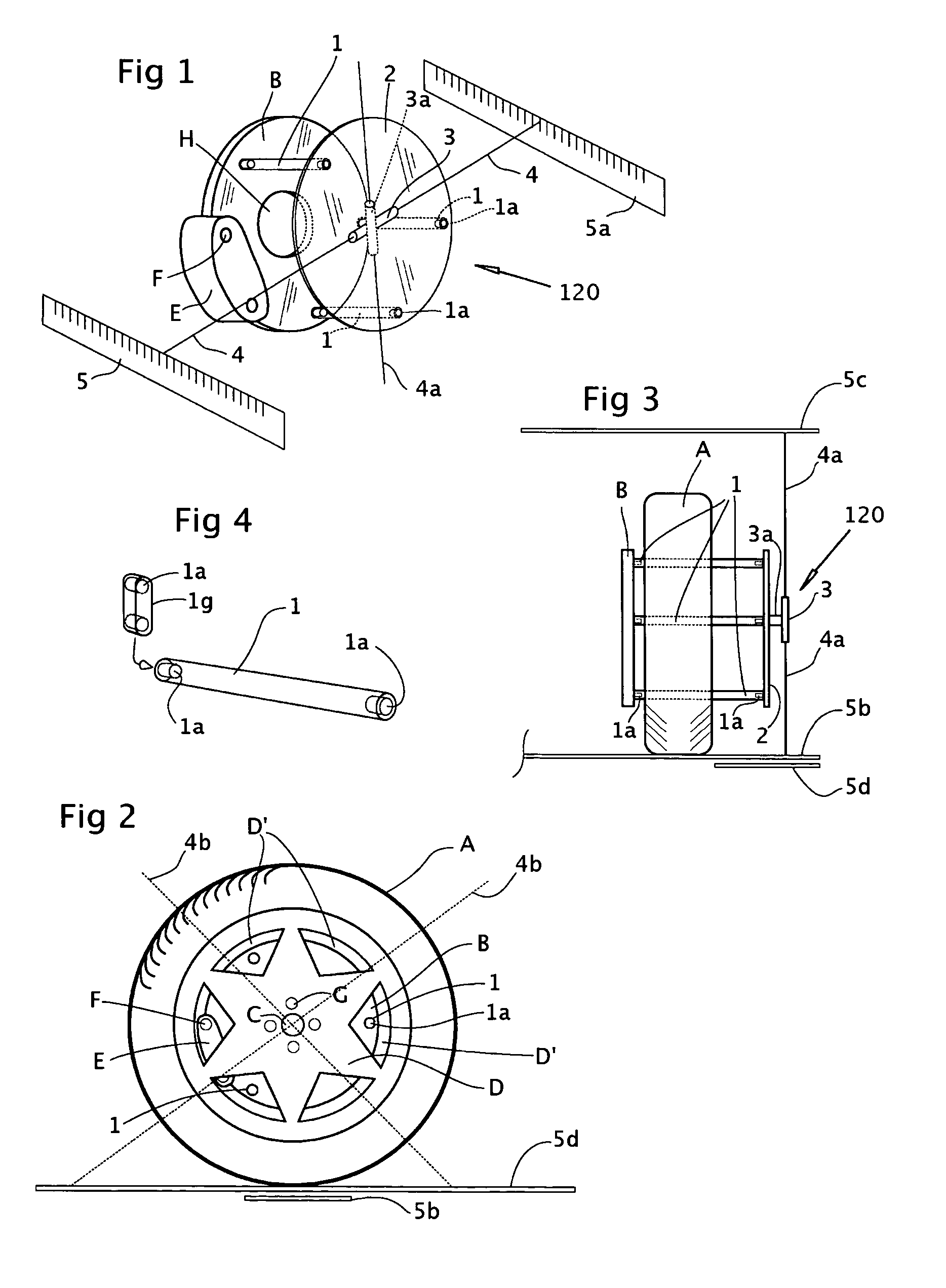
[0030] Checking alignment of wheels using the present gauge is done from the perspective of the wheel's disc brake rotor B, which is necessarily precisely planar with the wheel. In the preferred embodiment shown in FIGS. 10-15, several equal length, square-ended extension rods 1 having magnets la at each end are used. The inboard ends of these rods 1 pass through wheel openings D′ and attach to rotors B. Plate 2 rests on ground G and attaches to the outboard ends of these rods 1. Plate 2 is therefore planar and parallel to rotor B and to wheel A and serves as the reference surface onto which alignment arms 2a are mounted to conduct the wheel alignment check.

[0031] Two alignment...


PUM


Abstract

The present invention is a wheel alignment gauge for checking the ‘toe’ and ‘camber’ of the wheels. The gauge can be used with the vehicle on the ground. The gauge uses three identical magnet-ended extension rods which are inserted through the vent holes or spokes of the wheels. The rod's inboard ends magnetically attach to the disc brake rotor surface leaving the outboard ends clear of the vehicle's wheel and bodywork. Flat plates rest on the ground and magnetically attach to the outboard ends to create a plane parallel to the rotor and wheel. Laser-ended alignment arms magnetically attach to the plates, are level, and have forward ends that extend beyond the front of the vehicle allowing the lasers to project ate target sheets centered on the lasers. Each arm also has a perpendicular location arm that contacts the front of the wheel (or rotor when the wheels are removed). The laser's dots provide a off-center measurement, which, along with the arm's spacing, one can calculate the trigonometric SINE of the wheel's angle. The gauge can be quickly changed from vertical to horizontal for camber or toe measurements respectively. If adjustment is required, the vehicle is raised on its suspension, the wheels are removed and the gauge re-attached to locate on the rotors to direct alignment adjustments.

Description

FIELD OF THE INVENTION [0001] A low-cost gauge or jig for checking the wheel alignment of cars and other vehicles while they are on the ground. The gauge uses the disc brake rotor as the reference plane for alignment. BACKGROUND OF THE INVENTION [0002] Wheel alignment saves fuel, provides safer steering and braking, and reduces tire wear. Existing wheel alignment machines are large, expensive and require a large dedicated space (bay) and highly qualified operators. There is a need for a reasonably accurate and low priced gauge that small shops and gas / service stations can quickly use to check wheel alignment as a routine service for customers, and to guide wheel alignment after replacing shock absorbers, struts, ball joints, steering-rod-ends and other suspension-steering components. SUMMARY OF THE INVENTION [0003] The present invention is a gauge that uses one or more extension rods of equal length that are square ended with magnets. The rods pass through the vent or spoke openings...

Claims


Application Information

Patent Timeline
Patent Type & Authority Applications(United States)
IPC IPC(8): G01B5/24
CPCG01B5/255
Inventor MACKELVIE, WINSTON
Owner MACKELVIE WINSTON
Why Eureka
Try Eureka