Liquid-cooling heat dissipation assembly

a technology of heat dissipation assembly and liquid cooling, which is applied in the direction of indirect heat exchangers, domestic cooling devices, lighting and heating devices, etc. it can solve the problems of affecting the compact trend of computers, the bulky i>a /i> formed is bulky and difficult to assemble, and the expansion of the connection way of the construction and motherboard, so as to achieve speed up the heat exchange cycle and enhance the heat dissipation efficiency

Inactive Publication Date: 2006-08-24
CHEMTRON RES
View PDF4 Cites 41 Cited by
  • Summary
  • Abstract
  • Description
  • Claims
  • Application Information

AI Technical Summary

Benefits of technology

[0008] The present invention provides a liquid-cooling heat dissipation assembly, which comprises a liquid cooling array module, a liquid driving module and a cooling plate module integrated into an assembly. A through runner keeps the cooling liquid to flow continuously. The heat exchange cycle can be speeded up and the heat dissipation efficiency can be enhanced.

Problems solved by technology

Beside performance issue, the product appearance, the construction and motherboard connection ways are also under extensive exploited.
The liquid-cooling heat dissipation system 100a thus formed is bulky and hard to assemble.
This is adverse to the compact trend of computer.

Method used


Image

  • Liquid-cooling heat dissipation assembly
  • Liquid-cooling heat dissipation assembly
  • Liquid-cooling heat dissipation assembly

Examples


Embodiment Construction

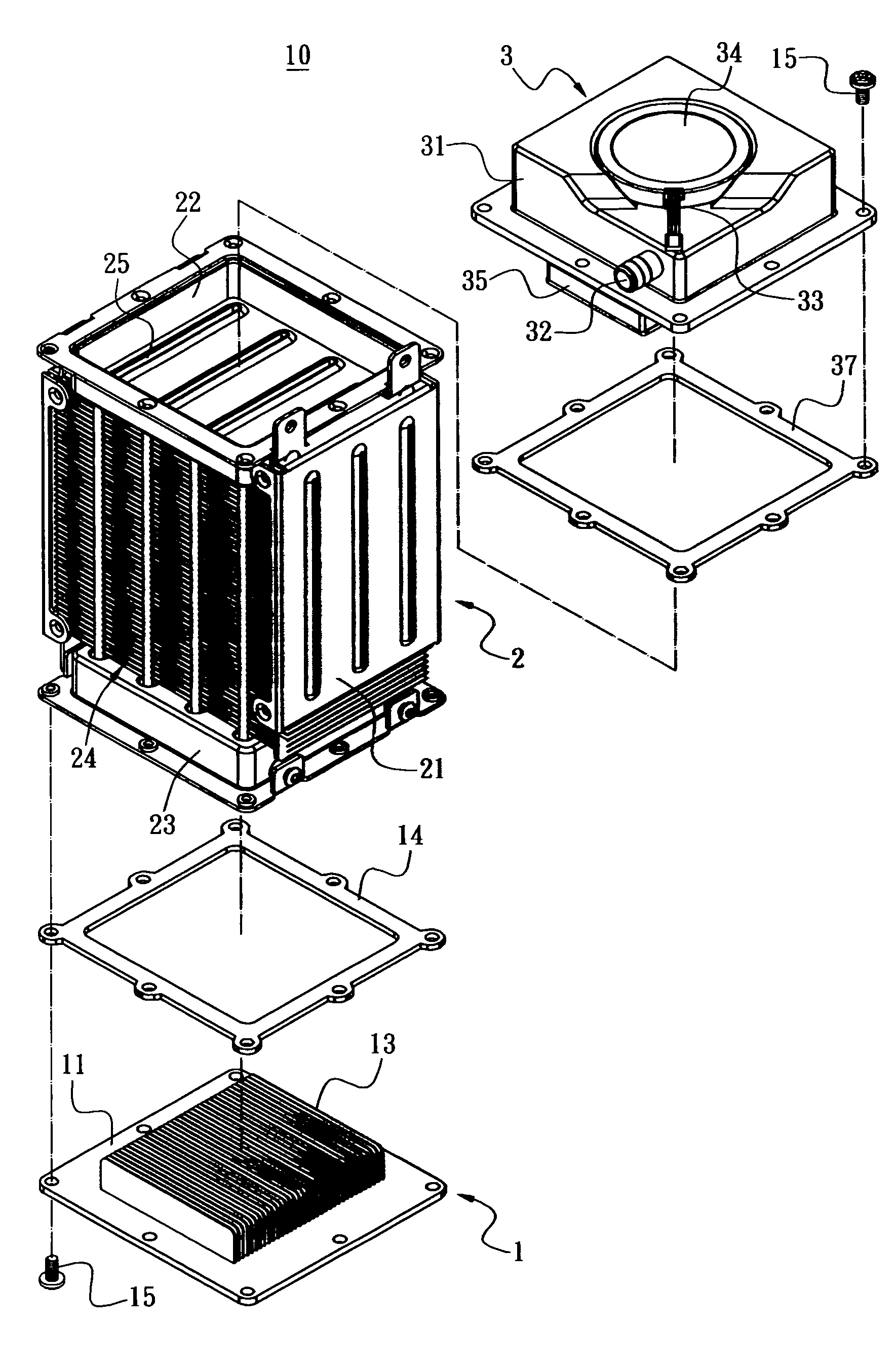
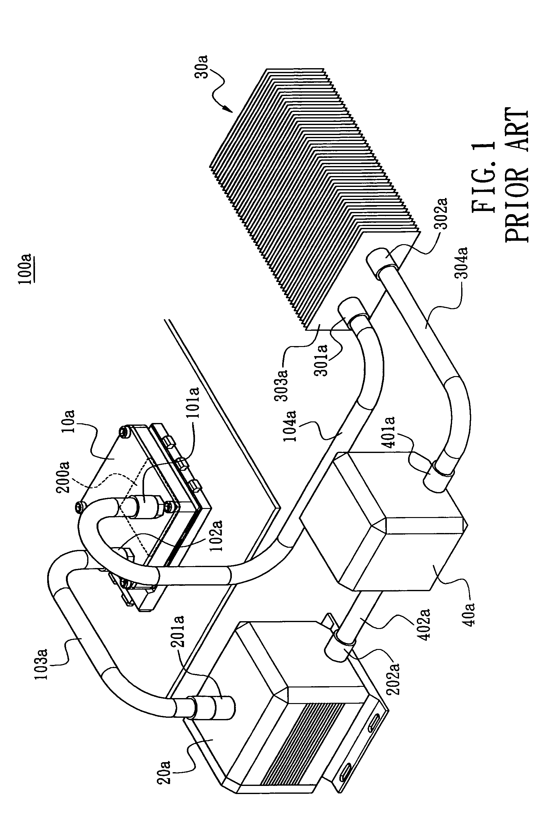
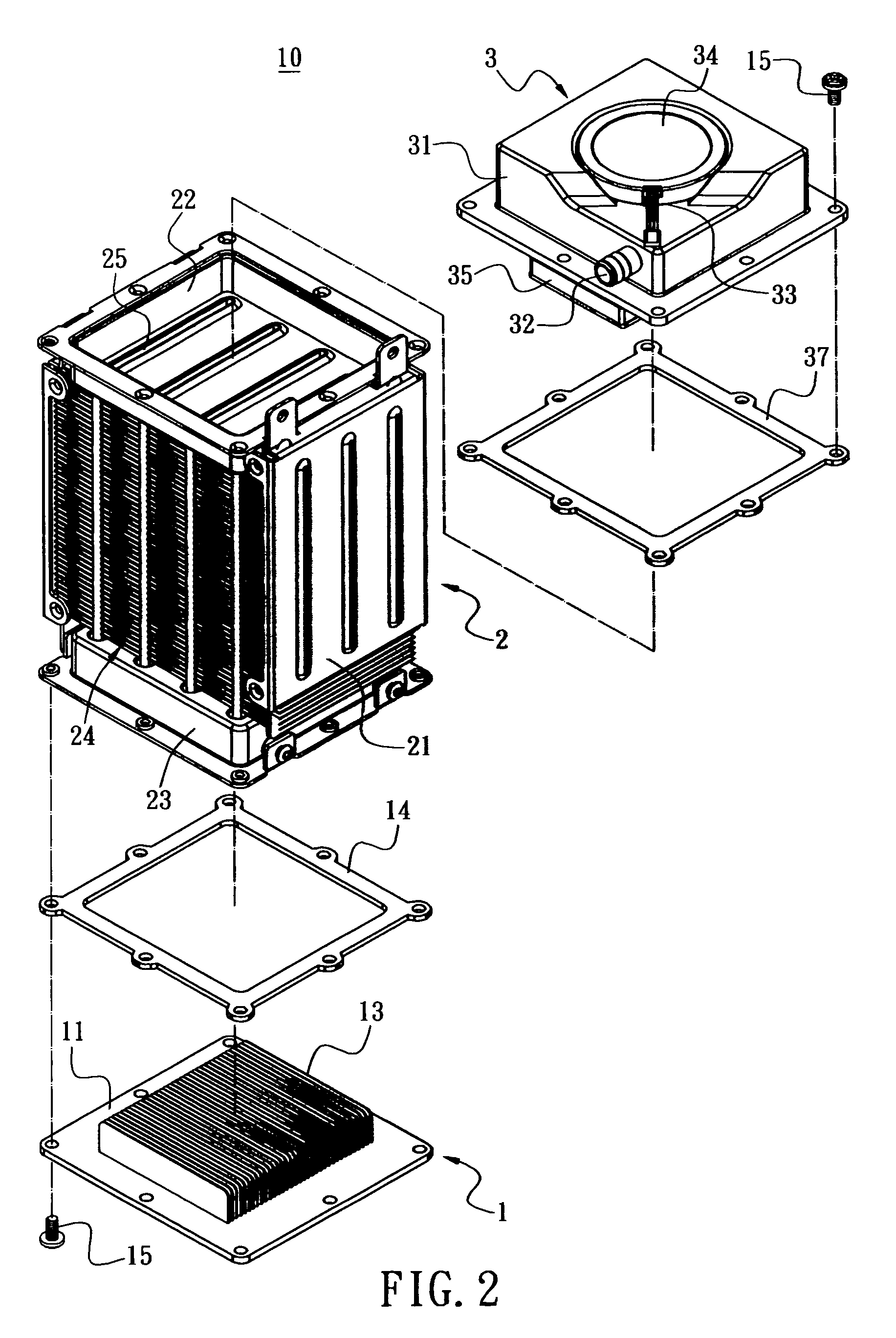
[0020] As shown in FIG. 2, the liquid-cooling heat dissipation assembly according to the present invention is used for heat dissipation of a CPU 20 shown in FIG. 7. The liquid-cooling heat dissipation assembly according to the present invention comprises, from bottom to top order, a cooling plate module 1, a liquid cooling array module 2, a liquid driving module 3 and runners define among those modules.

[0021] The liquid cooling array module 2 comprises a box 21 with an upper cover 22 and a lower cover 23 on top and bottom sides, respectively. A plurality of heat-dissipating fins 24 are provided at center of the box 21 and runners 25 are defined between the heat-dissipating fins 24. Both ends of the runner 25 are communicated with the upper cover 22 and the lower cover 23. In the shown embodiment, the cool liquid in the upper cover 22 is conveyed to the lower cover 23 through the two runners 25 at center portion; the cool liquid in the lower cover 23 is conveyed to the upper cover 2...


PUM


Abstract

A liquid-cooling heat dissipation assembly includes a liquid cooling array module with an upper cover and a lower cover on top and bottom sides of the liquid cooling array module, respectively, a liquid driving module assembled to the upper cover of the liquid cooling array module, a cooling plate module assembled with the lower cover of the liquid cooling array module, a liquid passageway defined through the liquid cooling array module and the cooling plate module. The liquid cooling array module, the liquid driving module and the cooling plate module are integrated into assembly and a through runner keeps the cooling liquid to flow continuously. The heat exchange cycle can be speeded up and the heat dissipation efficiency can be enhanced.

Description

BACKGROUND OF THE INVENTION [0001] 1. Field of the Invention [0002] The present invention relates to a liquid-cooling heat dissipation assembly, and more particularly to a liquid-cooling heat dissipation assembly used for heat emitting device such as a CPU. [0003] 2. Description of Prior Art [0004] The compass are developed with more powerful function and computation speed. Beside performance issue, the product appearance, the construction and motherboard connection ways are also under extensive exploited. As downsize of form factor and increasing of processing speed, the heat dissipation for central processing unit (CPU) is also an important issue to solve. [0005]FIG. 1 shows a perspective view of a prior art liquid-cooling heat dissipation system 100a. As shown in this figure, the liquid-cooling heat dissipation system 100a comprises a heat dissipation stage 10a, a water outlet 101a and a water inlet 102a on both ends of the heat dissipation system stage 10a, respectively, a duct ...

Claims


Application Information

Patent Timeline
Patent Type & Authority Applications(United States)
IPC IPC(8): F25B21/02F25D23/12
CPCF28D2021/0029F28D2021/0031H05K7/20263
Inventor DUAN, QIANG-FEIJIANG, TAI-YANG
Owner CHEMTRON RES
Why Eureka
Try Eureka