Insertable wall mounted computing apparatus

a computing apparatus and wall mount technology, applied in the field of modular wall or floormounted computing apparatuses, can solve the problems of low reliability, poor information and physical security, high cost, etc., and achieve the effect of easy deployment, minimal connected wiring, and minimal or no desktop spa

Inactive Publication Date: 2006-08-24
CHIP PC ISRAEL
View PDF1 Cites 45 Cited by
  • Summary
  • Abstract
  • Description
  • Claims
  • Application Information

AI Technical Summary

Benefits of technology

[0036] There exists a need for a computing device which for providing organizations and installation sites with a simple thin-client computing device that has minimum connected wiring and takes minimum or no desktop space. A computing device that can be easily deployed over existing or new network infrastructure, a device that requires minimal and simple installation.

Problems solved by technology

Desktop PCs brought not only access to information and increased productivity, but also many inherent problems.
These problems include: high costs, low-reliability issues, poor information and physical security, high power consumption and production of heat, noise, electromagnetic radiation, wasted space and poor central management.
Installation of This type of thin-client appliance is complex, time consuming and cumbersome due to the necessity to connect all the cables.
While this option saves the video cable connection and also reduces desktop space, it suffers from the inherent maintenance problems of coupling the two functions together.
This type of integration tends to complicate maintenance and to increase the solution price.
This solution is undesirable since keyboards are susceptible to mechanical failures and fluid damages, therefore maintenance problems using this combination are unavoidable.
This method is undesirable due to technical and operational problems including heavy weigh and high temperature that interfere with the mouse function and the need to connect many cables.

Method used


Image

  • Insertable wall mounted computing apparatus
  • Insertable wall mounted computing apparatus
  • Insertable wall mounted computing apparatus

Examples


Embodiment Construction

[0081] The following detailed description is of the best presently contemplated modes of carrying out the present invention. This description is not to be taken in a limiting sense, but is made merely for the purpose of illustrating the general principles in accordance with the present invention. The scope of the present invention is best defined by the appended claims.

[0082] Further reference will now be made to the drawings, wherein exemplary embodiments of the present claimed invention are illustrated.

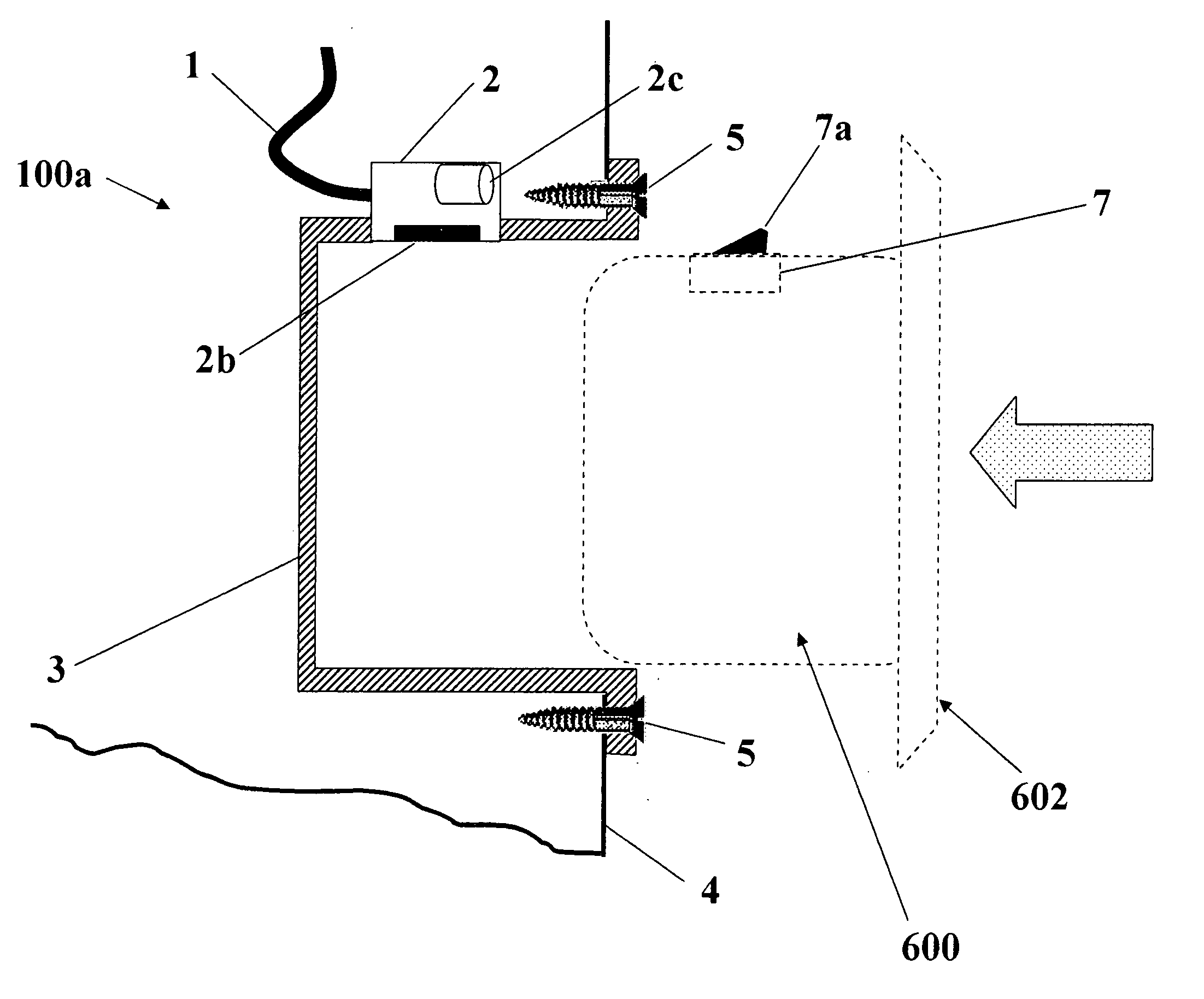
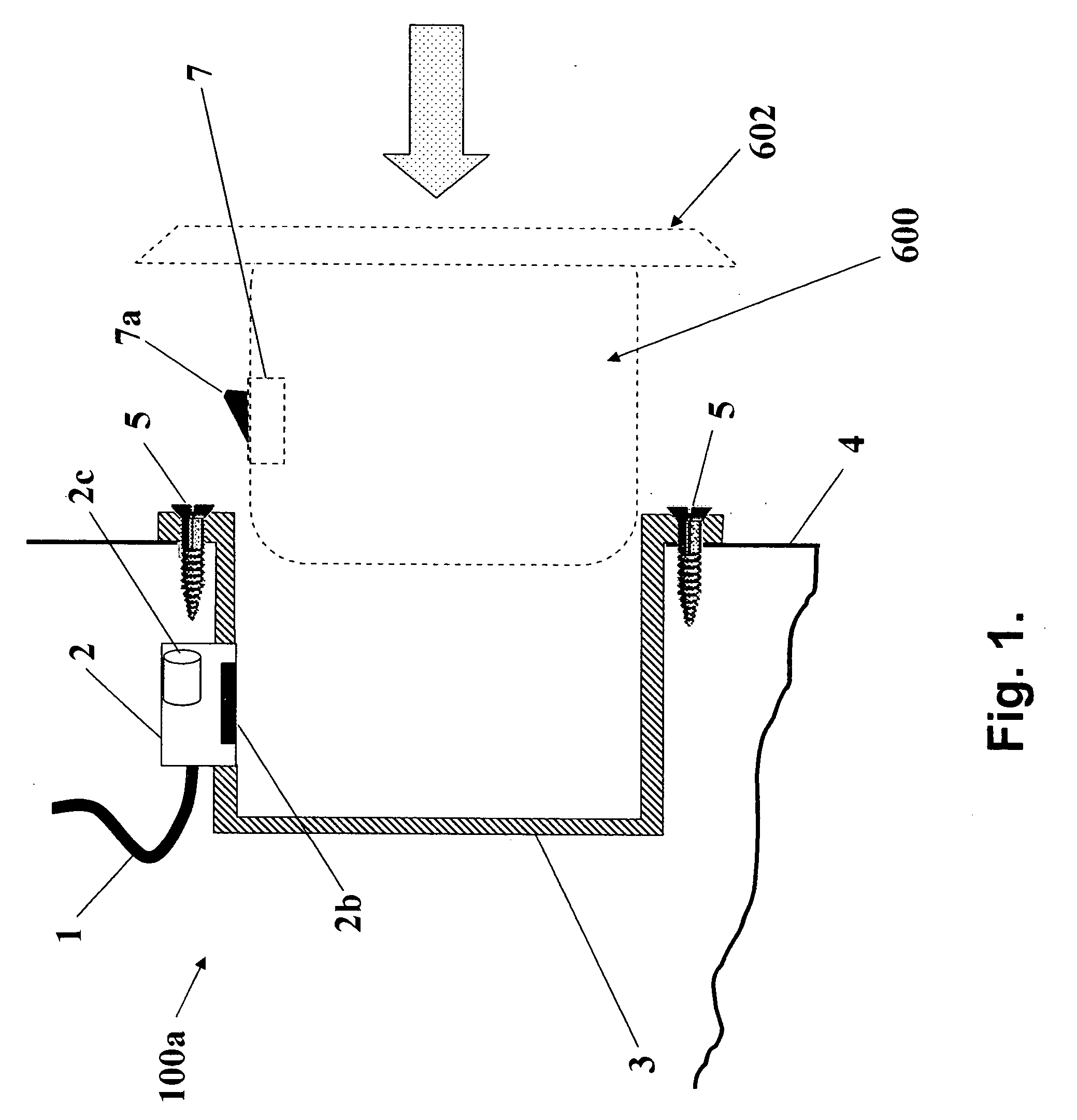
[0083] Reference is first made to FIG. 1 illustrates a cross-sectional view of the typical embodiment of the present invention showing the wall or floor mounted insert-housing 100a having network interface based on Ethernet LAN.

[0084] Wall or floor-mounted insert-housing 100a fit in a standard LAN jack hole (cutout) in the wall or in a floor-mounted box. Insert housing 100a is typically made of thin sheet metal or perforated plastic frame to secure the inset mechanically and to c...


PUM


Abstract

The present invention is directed to provide a compact computing apparatus fit to be mounted on the wall or floor adjacent to or embedded inside the LAN jack or a main power outlet. The compact computing apparatus is optionally connected at the backside through Ethernet cable to the building LAN and connected at the front side through cables or wirelessly to display, keyboard, mouse or other peripheral devices. In a typical embodiment of the present invention power to the computing apparatus is supplied through the LAN cable. Another embodiment of the present invention utilizes a wall or floor mounted housing part comprising of an integrated LAN connector. In the preferred embodiment of the invention the computing apparatus has layered structure.

Description

[0001] The present invention is a continuation-in-part of and claims the benefit of earlier U.S. provisional patent application Ser. No. 60 / 654,559 filed on Feb. 18, 2005 by Aviv Soffer.FIELD OF THE INVENTION [0002] The present invention is related generally to system of modular wall or floor-mounted computing apparatuses that among other functions replaces standard desktop PCs and enables computer user to access and use local and remote applications. More specifically, this invention relates to a thin-client type computing apparatus built inside or in conjunction with a LAN or mains jack and connected to the building LAN system infrastructure or the existing power lines network at one side and to the user interaction and peripheral devices on the other side. BACKGROUND OF THE INVENTION [0003] Desktop personal computers (PC) are essential working tools for many professionals today. Desktop PCs brought not only access to information and increased productivity, but also many inherent ...

Claims


Application Information

Patent Timeline
Patent Type & Authority Applications(United States)
IPC IPC(8): H02G3/08
CPCG06F1/16H01R13/66H01R23/10H01R27/02H01R2201/02H01R2201/04H02G3/123H04B3/56H04B2203/5483H04L12/10H04W88/02G06F1/00H02G3/08
Inventor AVIV, SOFFER
Owner CHIP PC ISRAEL
Why Eureka
Try Eureka