

Pipes, systems, and methods for transporting hydrocarbons
a technology of hydrocarbons and pipelines, applied in the direction of instruments, lighting and heating apparatus, and wellbore/well accessories, etc., can solve the problems of reducing the efficiency of pipelines, reducing the flow rate of produced fluid, and increasing pressure, so as to reduce the force required
- Summary
- Abstract
- Description
- Claims
- Application Information
AI Technical Summary
Benefits of technology
Problems solved by technology
Method used
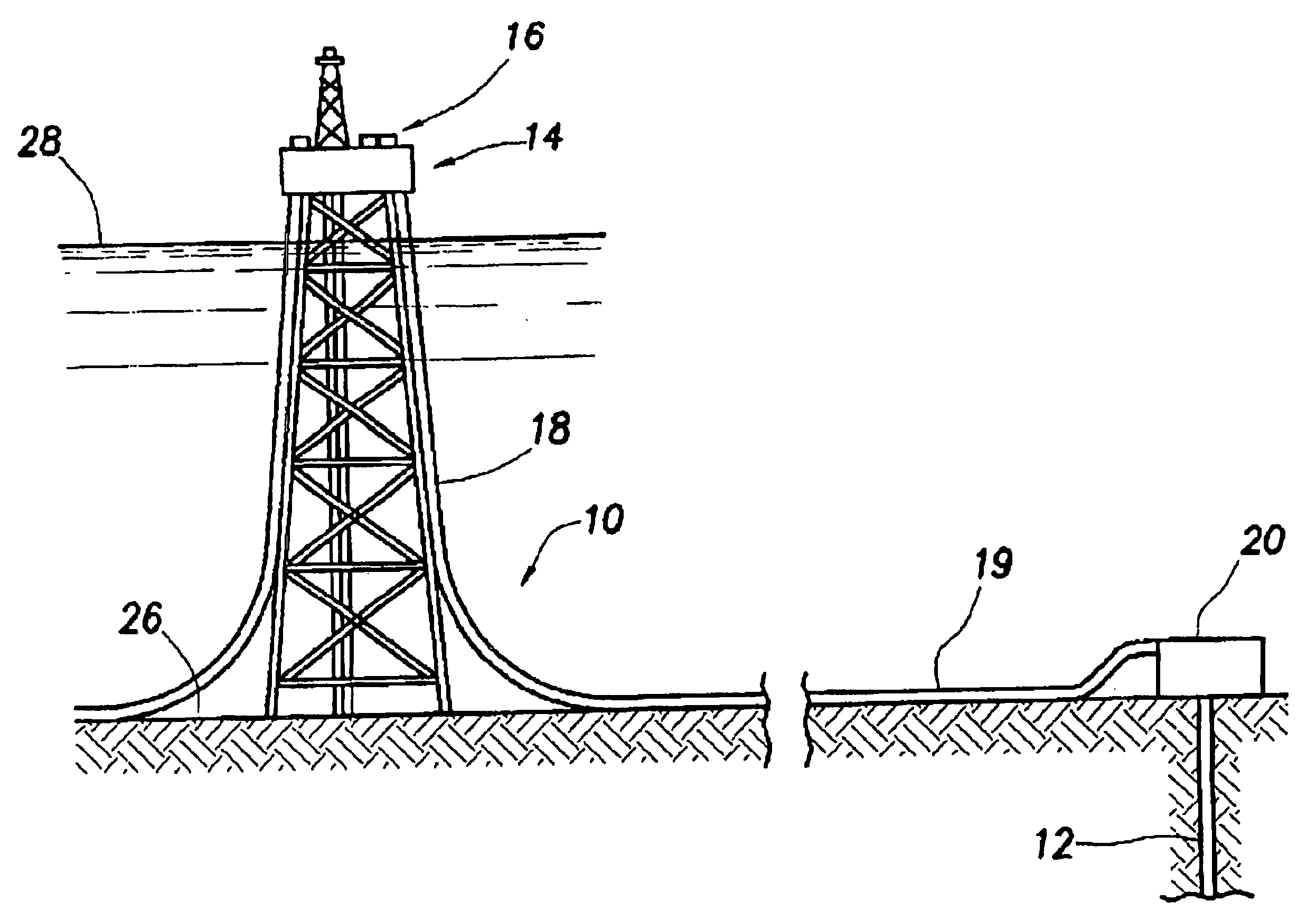
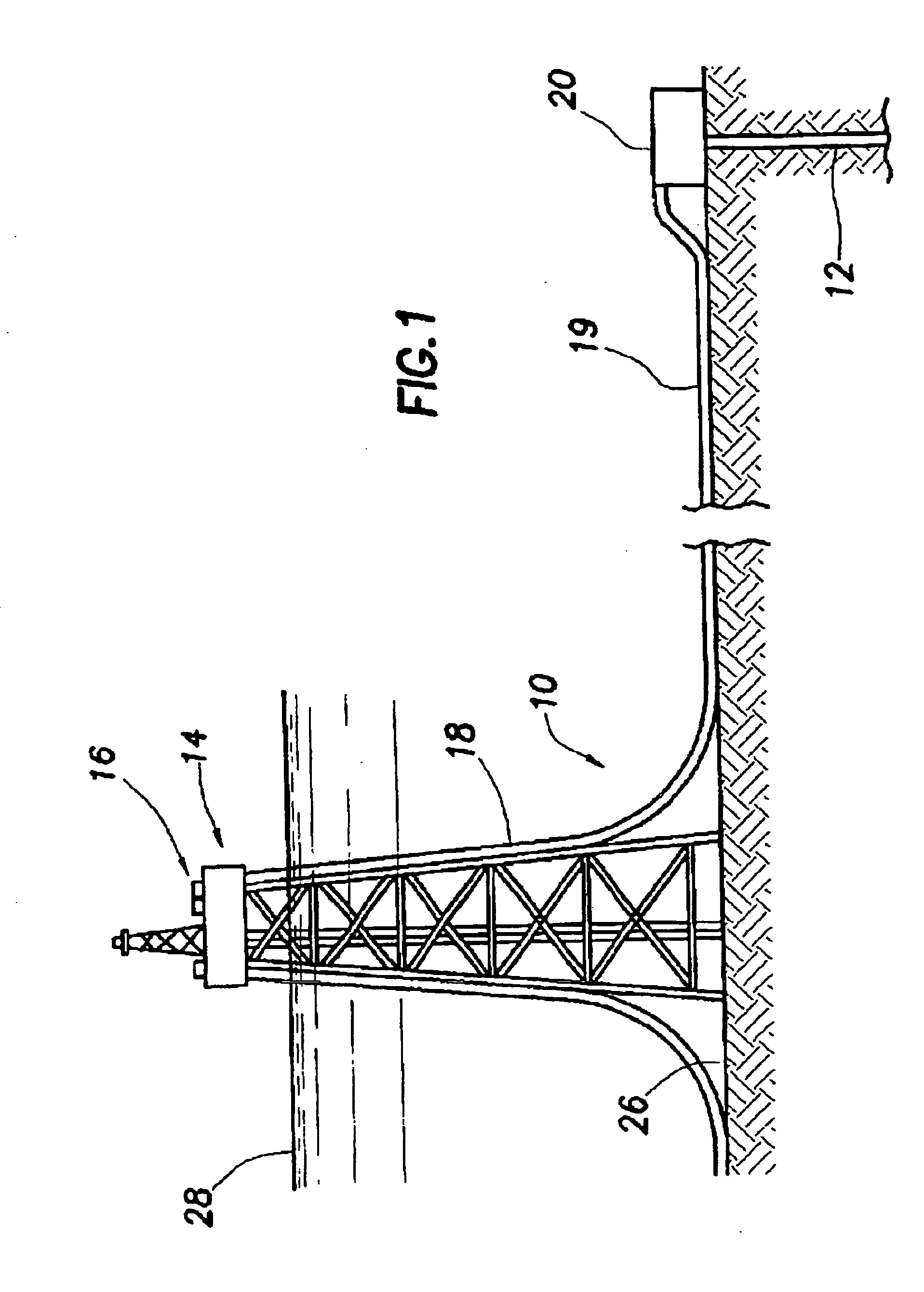
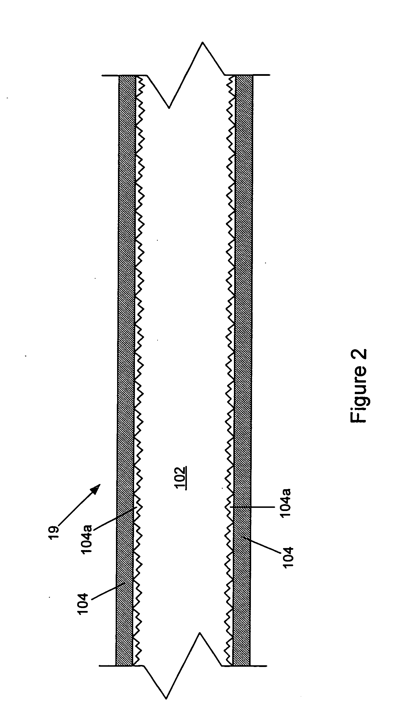
Image

Examples
example
[0076] A flow loop for deposition testing was used. Test sections with different inner-wall roughness were installed. Deposition tests were conducted with a 6-day period with temperature-controlled pumping of a waxy crude oil from a deepwater field in the Gulf of Mexico. Summary results are shown in FIG. 13. In FIG. 13, “White” diamonds denote a PASS in a deposition test (i.e., zero or insignificant deposition), “Gray” triangles denote a MARGINAL result, and “Black” diamonds denote a FAIL (i.e., significant and quantifiable deposition). The x value is the Ra and the y value, wall shear stress, is calculated from fluid properties, flow rates, and pipe diameter. As FIG. 13 indicates, the said smooth Pipes B-D used in the test section of the flow loop showed significant reduction in deposition compared to smooth Pipe A (test FAIL). It should be noted that Pipe B is considerably smoother than Pipe A, traditional pipe. As FIG. 13 further indicates, the said smooth Pipe D used in the test...
PUM
 Abstract
Description
Claims
Application Information