Hot fill container with restricted corner radius vacuum panels

a vacuum panel and hot filling technology, applied in the field of blow molding containers, can solve the problem of reducing the opportunity for vacuum induced changes in the conformation of the central portion of the vacuum panel to propaga

Inactive Publication Date: 2006-08-24
BALL CORP
View PDF81 Cites 86 Cited by
  • Summary
  • Abstract
  • Description
  • Claims
  • Application Information

AI Technical Summary

Benefits of technology

[0005] These several needs are satisfied by a container of the present invention, which has a finish adapted to receive a closure sealing the container, a neck situated below and supporting the finish, a shoulder portion situated below the neck, a base, and a body portion connecting the shoulder portion to the base. The body portion includes upper and lower margins defining a label mount area between the margins, the label mount area including a plurality of inwardly recessed vacuum panels separated by vertical posts. Each of the vacuum panels includes an upper edge and a lower edge, each edge being spaced from the upper and lower margins of the label mount area. At least one indented reinforcing ring, which can be circumferentially continuous or discontinuous, separates the upper and lower edges of the vacuum panels from the adjacent margins of the label mount area. The upper and lower edges of each vacuum panel have an included inclined margin, while the lateral edges of each vacuum panel have substantially radial margins. The corners of each vacuum panel are small as compared to the inclined margins of the panels, which reduces the opportunity for vacuum induced changes in conformation of the central portion of the vacuum panel to propagate outward from the corners.

Problems solved by technology

The corners of each vacuum panel are small as compared to the inclined margins of the panels, which reduces the opportunity for vacuum induced changes in conformation of the central portion of the vacuum panel to propagate outward from the corners.

Method used


Image

  • Hot fill container with restricted corner radius vacuum panels
  • Hot fill container with restricted corner radius vacuum panels
  • Hot fill container with restricted corner radius vacuum panels

Examples


Embodiment Construction

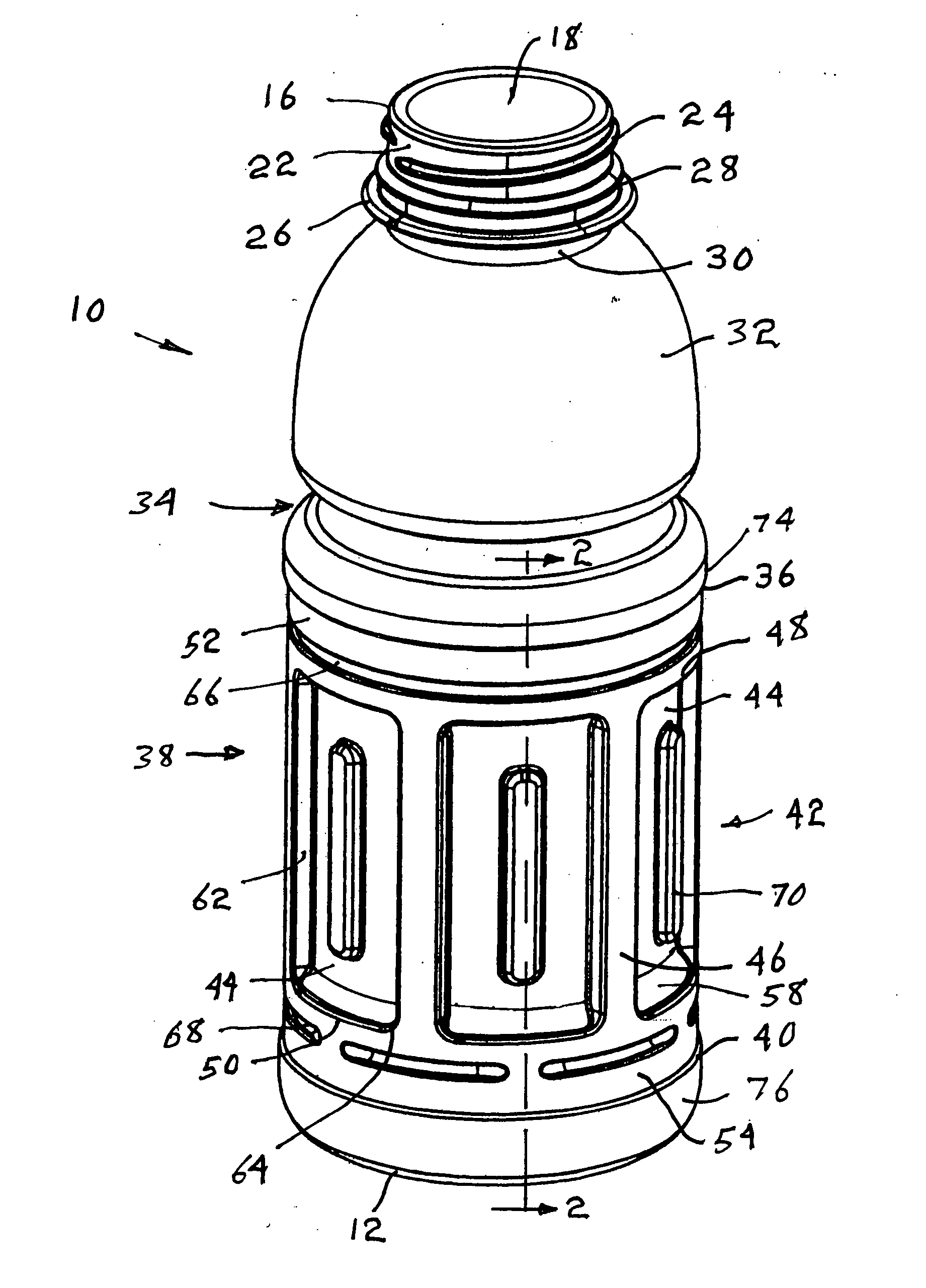
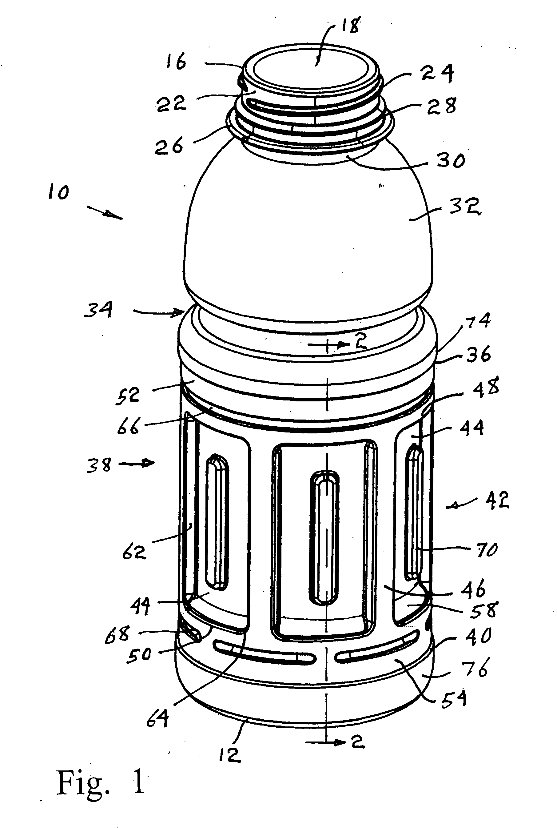
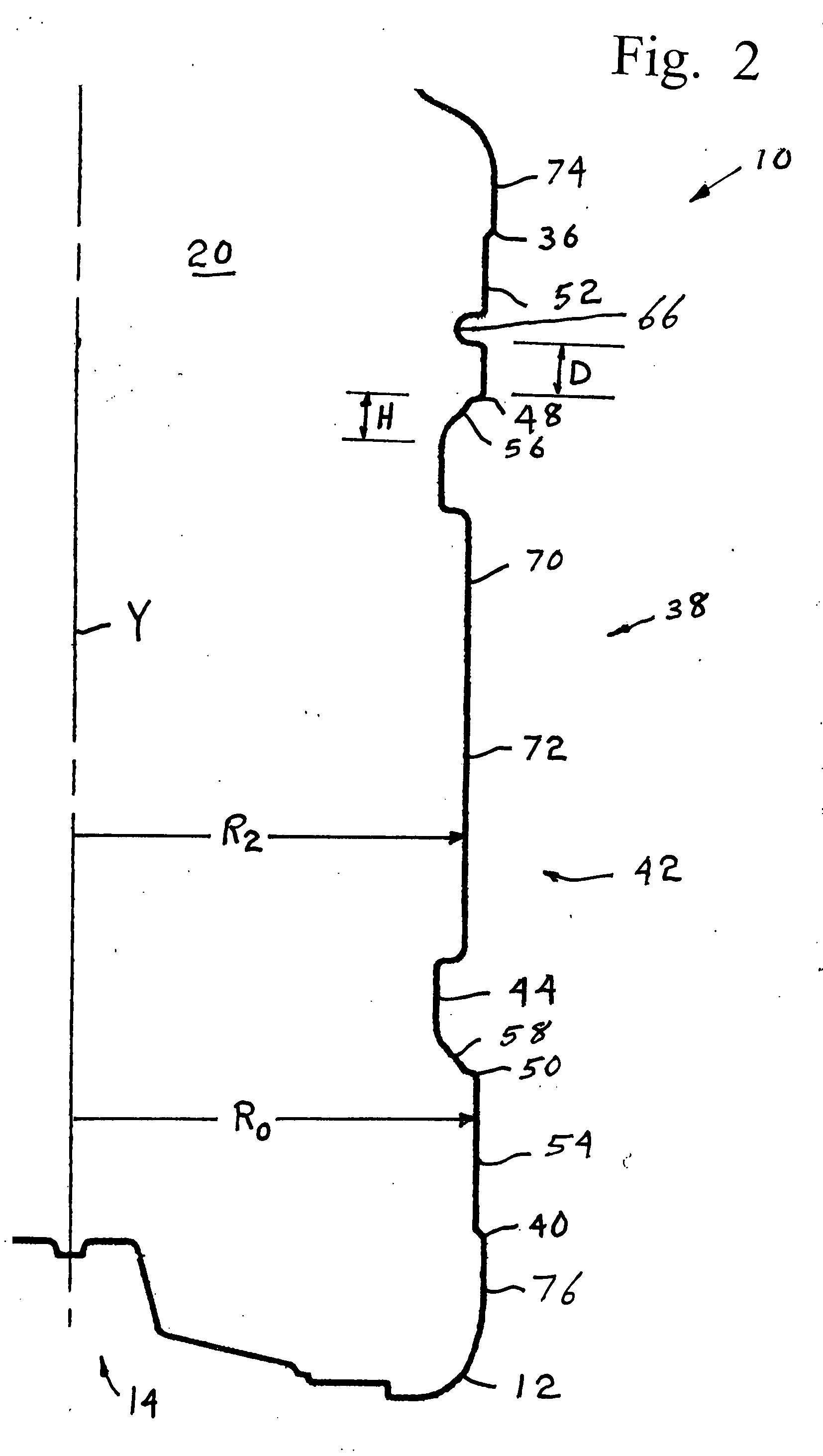
[0014] A thin-walled hot-fill container 10 of the present invention is shown in FIGS. 1, 2 and 4 to include a base 12 on a lower end 14 for generally supporting the container on any underlying substrate such as a shelf or table. An upper end 16 of the container 10 includes an open mouth 18 leading to the interior 20 of the container 10. The mouth 18 is surrounded by a finish 22 that is shown to include a thread 24 for receiving a threaded cap, not shown. A support ring 26 is located at a lower margin of the finish 22, and a pilfer-indicating band engagement ring 28 is located just above the support ring 26. A neck portion 30 is located immediately below the support ring 26. A shoulder portion 32 including a manual grip indention 34 is unitarily joined to the neck portion 30. The shoulder portion 32 is joined by margin 36 to a side wall portion 38 that extends from the shoulder portion 32 down to another margin 40 joining the side wall portion 38 to the base 12. The base 12, margins ...


PUM


Abstract

A thin walled, plastic hot-fill container has a finish to receive a closure, a neck supporting the finish, a shoulder situated below the neck, a base, and a body between the shoulder and base. The body includes upper and lower margins defining a label mount area that includes a plurality of inwardly recessed vacuum panels separated by vertical posts. At least one indented reinforcing ring separates the upper and lower edges of the vacuum panels from the adjacent margins of the label mount area by a distance D. Each vacuum panel includes an inclined upper and lower margin of height H that is greater than distance D, and has corners defined by radius R, which is less than or equal to D. Lateral margins of each vacuum panel extend vertically between the corners and connect the adjacent posts to a central depressed region, each lateral margin being essentially perpendicular to the adjacent surface of the vacuum panel.

Description

BACKGROUND OF THE INVENTION [0001] The present invention relates to blow-molded containers of biaxially oriented thermoplastic materials, typically polyethylene terephthalate, that are especially adapted to be filled with a hot liquid or semi-liquid product and hermetically sealed, and which are generally referred to as thin-walled hot-fill containers. The invention particularly relates to improvements in container design to achieve a filled container that, when cooled, retains a desired container configuration despite the development of a partial vacuum within the container, and provides enhanced support of any label applied to the container even when subjected to sidewall impact. [0002] Thin-wall hot-fill containers are typically used for packaging of liquids which must be placed in the container while hot for aseptic packaging. During the filling process, the container is subjected to elevated temperatures and may be subjected to some small positive internal pressures. The contai...

Claims


Application Information

Patent Timeline
Patent Type & Authority Applications(United States)
IPC IPC(8): B65D90/02
CPCB65D1/0223B65D79/005B65D79/0084
Inventor GATEWOOD, ERIK E.TYREE, BRIAN D.LIVINGSTON, JOHN J.
Owner BALL CORP
Why Eureka
Try Eureka