Packet forwarding apparatus and communication bandwidth control method

a packet forwarding and control method technology, applied in electrical devices, digital transmission, data switching networks, etc., can solve the problems of insufficient inability to keep a consistent quality of communication across all sections of a packet routing path, and inability to ensure practicably sufficient qos control of rsvp-

Inactive Publication Date: 2006-08-24
HITACHI LTD
View PDF8 Cites 132 Cited by
  • Summary
  • Abstract
  • Description
  • Claims
  • Application Information

AI Technical Summary

Benefits of technology

[0030] In the preferable embodiment, the first communication node stores the priority information notified from said second communication node in association with a session identifier into said management table and procures a necessary free bandwidth to be allocated to a new session if free bandwidth of the tunn...

Problems solved by technology

However, because policies and parameters set for QoS differ for different packet forwarding apparatuses or network managers, it is difficult to keep a consistent quality of communication across all sections of a packet routing path.
However, traffic conditions in a network frequently change over time and a QoS level, which was set when a session is initiated, is not always maintained until the end of a packet flow and, thus, the RSVP-TE does not assure practically sufficient QoS control.
Because a communication bandwidth required for QoS is allocated for each section in order from the upstream of the packet path, there is a possibility of selecting an alternate route which becomes useless in terms ...

Method used


Image

  • Packet forwarding apparatus and communication bandwidth control method
  • Packet forwarding apparatus and communication bandwidth control method
  • Packet forwarding apparatus and communication bandwidth control method

Examples


first embodiment

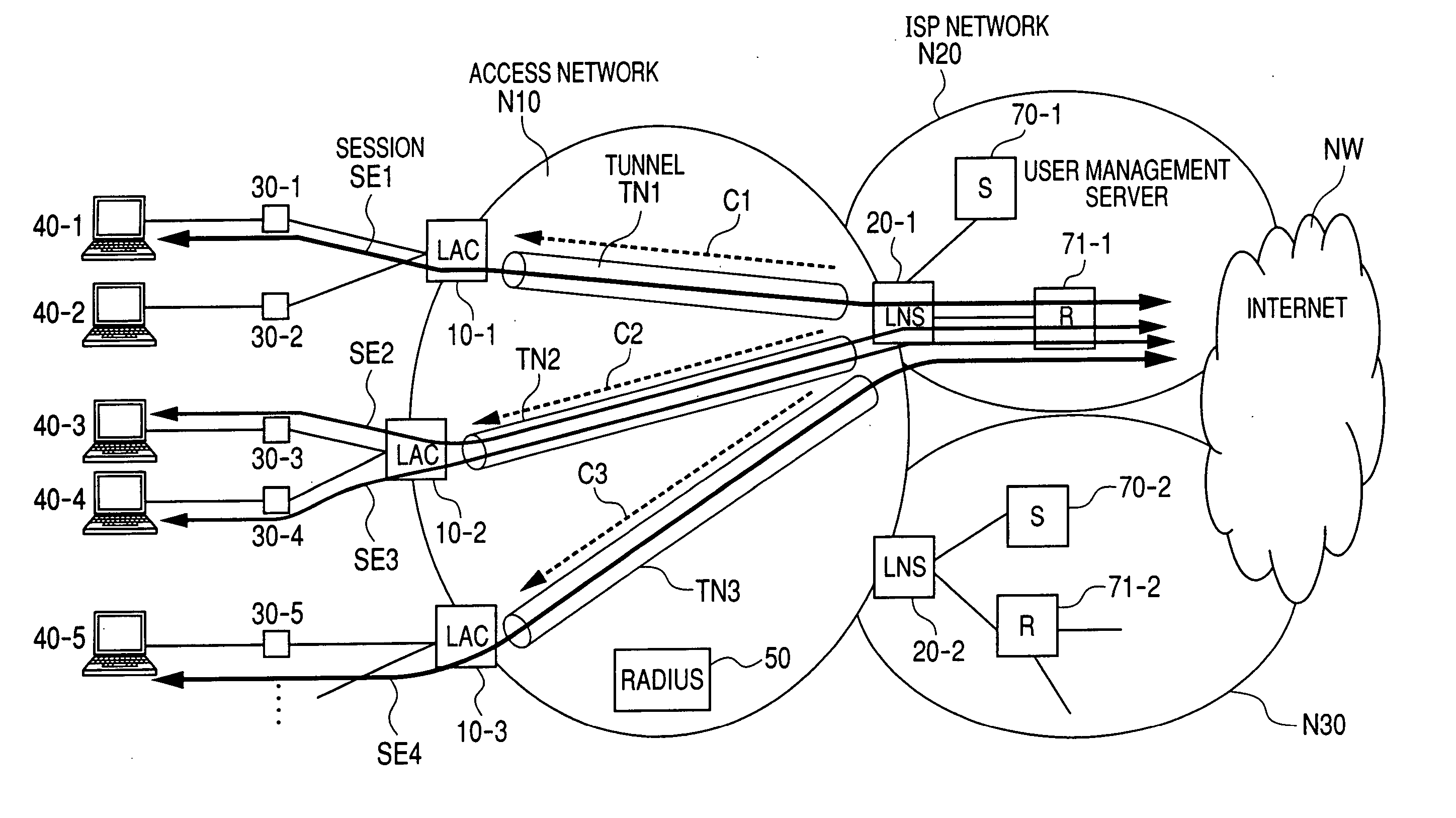
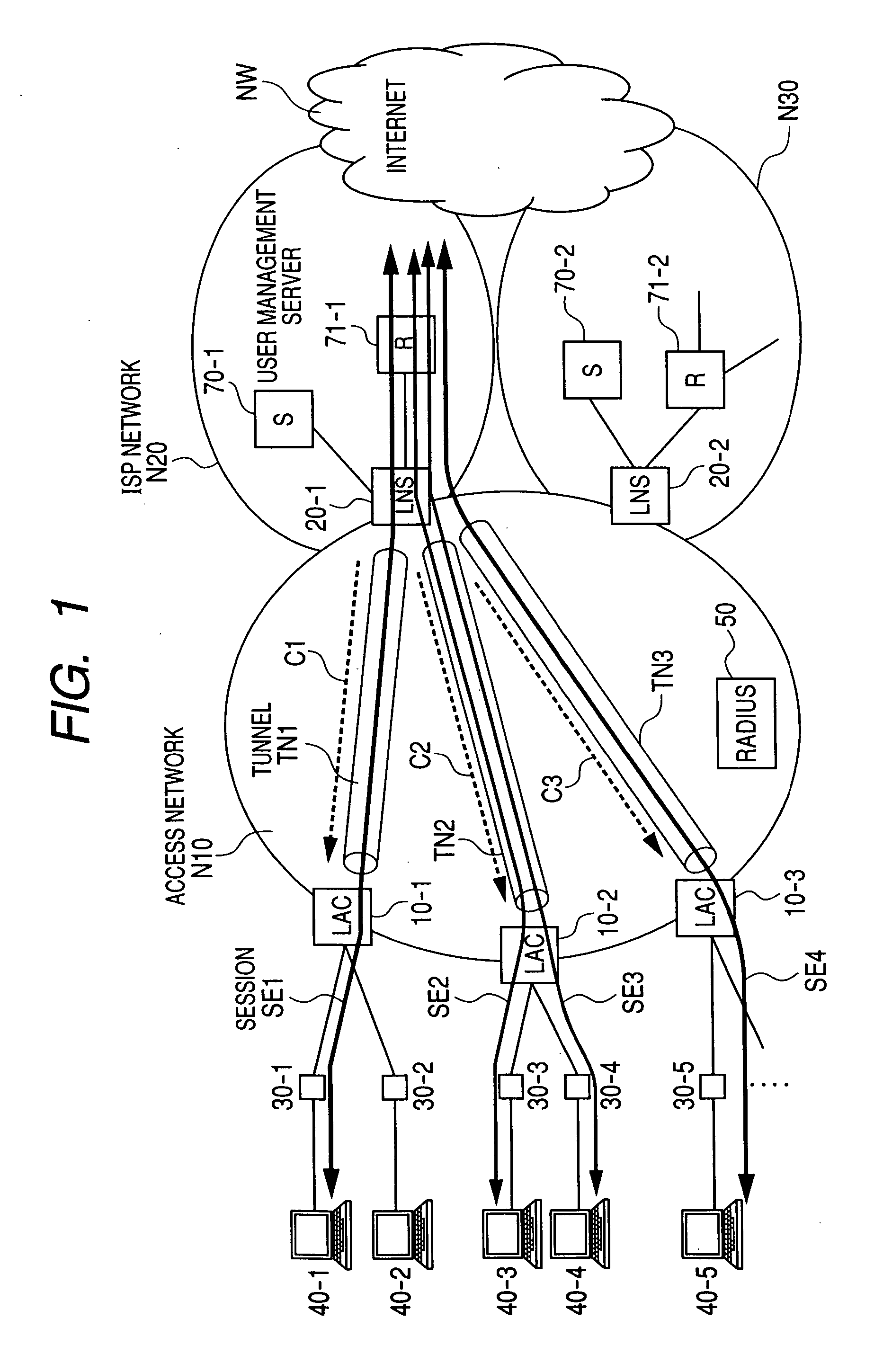
[0083] Now, a communication bandwidth control method for the sections of the tunnels through which packets are forwarded in the network architecture of FIG. 1 will be described below.

[0084] Upon receiving a communication request from a user terminal 40 via a private router 30, each LAC 10 (10-1 to 103) establishes a connection (tunnel) to a LNS 20 corresponding to the ISP, to which the terminal user subscribed, to encapsulate and forward received packets to the LNS. If there is already a tunnel between the LAC 10 and the LNS 20, a new communication session for each user or service can be simply set up through the existing tunnel and there is no need to establish a new tunnel.

[0085] In the access network N10, since the sessions from a plurality of users toward the ISP networks N20-1 and N20-2 are terminated on the LNSs 20-1 and 20-1 serving as the nodes for connecting to the ISP networks N20, traffic concentrates on these nodes. In the present invention, the LNS 20-1 (20-2) refers t...

second embodiment

[0131] In the second embodiment, when the result of user authentication was received from the user management server 70, the LNS 20 returns a response packet (ACK) for the user authentication request to the LAC 10 (SQ33). When it is judged that the user authentication was successful from the response packet, the LAC 10 sends an authentication response packet (PPP CHAP success) to the private router 30 (SQ34).

[0132] Having received the authentication response packet, the private router 30 sends an IPCP Configuration-Request to the LNS 20 (SQ35). When the LNS 20 sends an IPCP Configuration-ACK including the IP address to be used by the user terminal to the private router 30 (SQ36), the setup procedure for communication is completed. After that, the user terminal 40 can transmit user packets to the LNS 20 (SQ37).

[0133] In the second embodiment, upon receiving a user packet, the LNS 20 forwards the received packet to the ISP network (SQ38) and, concurrently, determines whether a bandwi...

third embodiment

[0146]FIG. 16A and FIG. 16B show examples of a communication status management table 700 prepared in a LNS 20 in the

[0147] As shown in FIG. 16A, the communication status management table 700 indicates, in association with tunnel ID 701, the number of sessions 702 and allocated bandwidth 703. Here, the number of sessions 702 specifies the number of sessions multiplexed through the same tunnel having the tunnel ID 701. The allocated bandwidth 703 specifies the bandwidth pre-allocated to each tunnel depending on the number of users who utilize the same tunnel. In the case where each LAC forms one tunnel between the LAC and each LNS corresponding to an ISP network, the allocated bandwidth 703 indicates the bandwidth allocated in accordance with the number of users for each ISP accommodated by the LAC.

[0148] The feature of the third embodiment resides in that the maximum bandwidth 703 of each tunnel is controlled from the LNS 10 and bandwidth allocation to each session is controlled by ...


PUM


Abstract

In a network for forwarding user packets by a tunneling protocol, an egress edge node to which tunnels concentrate from a plurality of ingress edge nodes allocates a bandwidth to each of sessions multiplexed through each of the tunnels and notifies each of the ingress edge nodes of the allocated bandwidth, and the ingress node notifies private routers or terminal devices of the allocated bandwidth.

Description

CLAIM OF PRIORITY [0001] The present application claims priority from Japanese application serial No. 2005-045108, filed on Feb. 22, 2005, the content of which is hereby incorporated by reference into this application. BACKGROUND OF THE INVENTION [0002] (1) Field of the Invention [0003] The present invention relates to a packet forwarding apparatus and a communication bandwidth control method and, more particularly, to a packet forwarding apparatus and a communication bandwidth control method suitable for communication quality assurance for packets transmitted over a network comprising a plurality of nodes. [0004] (2) Description of Related Art [0005] Improvement of computer-based communications environment is evolving. Internet Protocol (IP) that is used worldwide is a communication protocol for a network layer of the OSI reference model. According to the IP, IP addresses are assigned to the line interfaces of apparatuses as terminals and relay nodes and each apparatus is identifie...

Claims


Application Information

Patent Timeline
IPC IPC(8): H04L12/56H04L12/54H04L12/66H04L47/2475H04L47/2491H04L47/724H04L47/80
CPCH04L12/5695H04L47/2408H04L47/745H04L47/765H04L47/803H04L47/808H04L47/825H04L47/70
Inventor MIZUTANI, MASAHIKOHINO, MASAYUKI
Owner HITACHI LTD
Why Eureka
Try Eureka